


Section 1
1-19
Geometry Modeling Considerations
The following geometry related modeling rules should be
remembered while using the plate/shell element
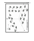
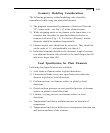
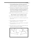
1) The program automatically generates a fictitious fifth node
"O" (center node - see Fig. 1.8) at the element center.
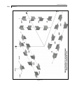
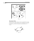
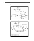
2) While assigning nodes to an element in the input data, it is
essential that the nodes be specified either clockwise or
counter clockwise (Fig. 1.9). For better efficiency, similar
elements should be numbered sequentially
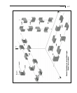
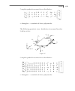
3) Element aspect ratio should not be excessive. They should be
on the order of 1:1, and preferably less than 4:1.
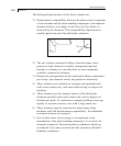
4) Individual elements should not be distorted. Angles between
two adjacent element sides should not be much larger than 90
and never larger than 180.
Load Specification for Plate Elements
Following load specifications are available:
1) Joint loads at element nodes in global directions.
2) Concentrated loads at any user specified point within the
element in global or local directions.
3) Uniform pressure on element surface in global or local
directions
4) Partial uniform pressure on user specified portion of element
surface in global or local directions
5) Linearly varying pressure on element surface in local
directions.
6) Temperature load due to uniform increase or decrease of
temperature.
7) Temperature load due to difference in temperature between top
and bottom surfaces of the element.