Section 2
2-35
VERIFICATION PROBLEM HAND CALCULATION
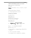
Manual / Code refers to AASHTO Manual .
Steel Design -
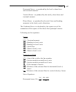
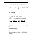
Member 1, Size W 12X26, L = 10 ft., a = 7.65 in
2
, Sz = 33.39 in
3
From observation Load case 1 will govern,
Fx = 25.0 kip (compression), Mz = 56.5 k-ft
Allowable Stress Calculation:
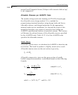
From Table 10.32.1A,
Bending Minor Axis:
Allowable minor axis bending stress:
FTY = FTZ = 0.55 x F
Y
= 19.8 ksi
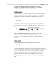
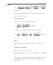
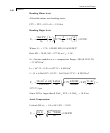
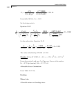
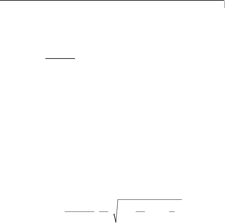
Bending Major Axis:
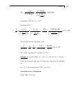
2
6
50 10
0.772 9.87 0.55
yc
b
cz y
xc yc
I
xC
Jd
FF
Sl I l
⎛⎞
⎛⎞
=+
⎜⎟
⎜⎟
⎝⎠
⎝⎠
≤
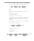
Where, C
b
= 1.75+ 1.05(M1/M2)+0.3x(M1/M2)
2
Here M1 = 0, so C
b
= 1.75
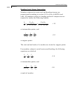
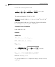
S
zc
=Section modulus w.r.t. compression flange =204/(0.5X12.22)
= 33.38789 in
3
I
YC
= tb
3
/12 = 0.38 x 6.49
3
/12 = 8.6564 in
4
J = (2 x 6.49x0.38
3
+ (12.22 – 2x0.38)x0.23
3
)/3 = 0.28389 in
4


