Section 5
5-239
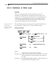
x = solution time step used in the step-by-step
integration of the uncoupled equations. Values
smaller than 0.00001 will be reset to the default
DT value of 0.0013888 seconds.
i = type number of time varying load (integer). Up to
136 types may be provided. ACCELERATION
indicates that the time varying load type is a
ground motion. FORCE or MOMENT indicates
that it is a time varying force or moment. This
number should be sequential.
Scale f
7
= The scale factor option multiplies all forces,
accelerations, and amplitudes entered, read or
generated within this Type. Primarily used to
convert acceleration in g’s to current units
(9.80665, 386.08858, etc.). Default is 1.0.
Save = The save option results in the creation of two files
(input file name with "Tim" and “Frc” extensions)
containing the history of the displacements of
every node (on “Tim”) and the history of the 12
end forces of every member and the history of the
support reactions (on “Frc”) of the structure at
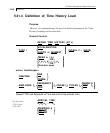
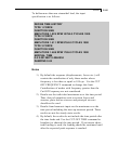
every time step . Syntax: TYPE 1 FORCE
SAVE
t
1
p
1
t
2
p
2
...= values of time(sec.) and corresponding force
(current force unit) or acceleration (current length
unit/sec
2
) depending on whether the time varying
load is a forcing function or a ground motion. If
the data is specified through the input file, up to
499 pairs can be provided for each type in the
ascending value of time. More than one line may
be used if necessary. However, if the data is
provided through an external file, an unlimited
number of time-force pairs may be specified. If
the first point is not at zero time, then the forces
before the first time (but after the arrival time) will
be determined by extrapolation using the first two
points entered. If the first point has a nonzero
force, there will be a sudden application of that
force over a single integration step (DT) at that


