General Description
Section 1
1-86
are chosen from this time ′0′ to n*tc in steps of "STEP" where n is
the number of cycles and tc is the duration of one cycle. STEP is a
value that the user may provide or may choose the default value
that is built into the program. STAAD will adjust STEP so that a
¼ cycle will be evenly divided into one or more steps. Users may
refer to section 5.31.4 of this manual for a list of input parameters
that need to be specified for a Time History Analysis on a
structure subjected to a Harmonic loading.
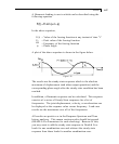
The relationship between variables that appear in the STAAD
input and the corresponding terms in the equation shown above is
explained below.
F
0
= AMPLITUDE
ω = FREQUENCY
φ = PHASE
1.18.3.6 Steady State and Harmonic Response
A structure [subjected only to harmonic loading, all at a given
forcing frequency and with non-zero damping] will reach a steady
state of vibration that will repeat every forcing cycle. This steady
state response can be computed without calculating the transient
time history response prior to the steady state condition.
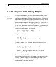
) ( sin)(
0
φ
ω
+
=
tRtR
The result, R, has a maximum value of R
0
and a phase angle
φ
.
These two values for displacement, velocity, and acceleration at each joint
may be printed or displayed
This analysis is performed using the modal superposition method.
Hence, all the active masses should be modeled as loads in order
to facilitate determination of the mode shapes and frequencies.
Please refer to the section above on
"mass modeling" for
additional information on this topic. In the mode superposition
analysis, it is assumed that the structural response can be obtained
from the "p" lowest modes.


