Section 5
5-389
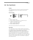
5.46 Size Specification
Purpose
This command provides an estimate for required section properties
for a frame member based on certain analysis results and user
requirements.
General Format:
*
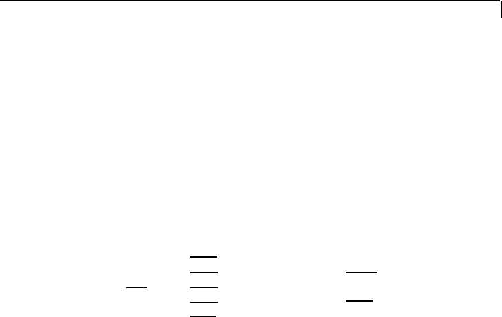
⎧WIDTH f
1
⎫
⎪DEFLECTION f
2
⎪ ⎧MEMBER member-list ⎫
SIZ
E ⎨LENGTH f
3
⎬ ⎨ ⎬
⎪BSTRESS f
4
⎪
⎩
ALL
⎭
⎩
SSTRESS f
5
⎭
where,
f
1
= Maxm. allowable width
f
2
= Maxm. allowable (Length/Maxm. local deflection) ratio
f
3
= Length for calculating the above ratio.
Default = actual member length.
f
4
= Maxm. allowable bending stress.
f
5
= Maxm. allowable shear stress.
The values must be provided in the current unit system.
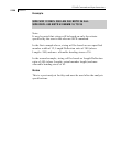
Description
This command may be used to calculate required section properties
for a member based on analysis results and user specified criteria. The
user specified criteria may include Member width, Allowable
(Length/Maxm. Deflection) Ratio, Maxm. allowable bending stress
and Maximum allowable shear stress. Any number of these criteria
may be used simultaneously. The output includes required Section
Modulus (about major axis), required Shear Area (for shear parallel to
minor axis), Maxm. moment capacity (about major axis), Maxm. shear
capacity (for shear parallel to minor axis) and Maxm. (Length/local
maxm. deflection) ratio.


