


STAAD Commands and Input Instructions
Section 5
5-380
ANGLE = Angle which determines direction of maximum
principal stress with respect to local X axis
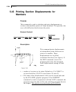
If the JOINT option is used, forces and moments at the nodal
points are also printed out in addition to the centroid of the
element.
The AT option may be used to print element forces at any specified
point within the element. The AT option must be accompanied by
f
1
and f
2
. f
1
and f
2
are local X and Y coordinates (in current units)
of the point where the stresses and moments are required. For
detailed description of the local coordinate system of the elements,
refer to Section 1.6 of this manual.
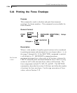
The PRINT ELEMENT FORCES command enables printing of
plate “corner forces” [ F
p
= K
p
• D
p
] in global axis directions.
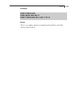
The PRINT ELEMENT (JOINT) STRESS SOLID command
enables printing of stresses at the center of the SOLID elements.
The variables that appear in the output are the following.
Normal Stresses : SXX, SYY and SZZ
Shear Stresses : SXY, SYZ and SZX
Principal Stresses : S1, S2 and S3.
Von Mises Stresses : SE
Direction cosines : 6 direction cosines are printed following
the expression DC, corresponding to the
first two principal stress directions.
The JOINT option will print out the stresses at the nodes of the
solid elements.
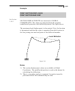
The PRINT MODE SHAPES command prints the relative joint
motions of each of the modes that were calculated. The maximum
motion is arbitrary and has no significance. Dynamic analysis will
scale and combine the mode shapes to achieve the final dynamic
results.