Section 5
5-107
5.22.1 Member Release Specification
Purpose
This set of commands may be used to fully release specific degrees
of freedom at the ends of frame members. They may also be used
to describe a mode of attachment where the member end is
connected to the joint for specific degrees of freedom through the
means of springs
.
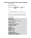
General format:
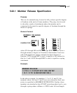
MEMBER RELEASES
*
⎧FX ⎫ * ⎧KFX f1 ⎫
⎧START ⎫ ⎪FY ⎪ ⎪KFY f2 ⎪
member-list
⎨END ⎬ ⎨FZ ⎬ ⎪KFZ f3 ⎪
⎩BOTH ⎭ ⎪MX ⎪ ⎪KMX f4 ⎪
⎪MY ⎪ ⎪KMY f5 ⎪
⎩MZ ⎭ ⎩KMZ f6 ⎭
where FX through MZ and KFX through KMZ represent force-x
through moment-z degrees of freedom in the member local axes
and f1 through f6 are spring constants for these degrees of
freedom. If FX through MZ is used, it signifies a full release for
that d.o.f, and if KFX through KMZ is used, it signifies a spring
attachment
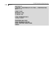
Example
MEMBER RELEASE
1 3 TO 9 11 12 START KFX 1000.0 MY MZ
1 10 11 13 TO 18 END MZ KMX 200.0
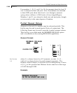
In the above example, for members 1, 3 to 9, 11 and 12, the
moments about the local Y and Z axes are released at their start
joints (as specified in MEMBER INCIDENCES). Further, these
members are attached to their START joint along their local x axis
through a spring whose stiffness is 1000.0 units of force/length.


