STAAD Commands and Input Instructions
Section 5
5-280
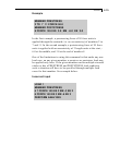
Correct Input
LOAD 1
MEMBER PRESTRESS
6 7 FORCE 100 ES 2 EM -3 EE 2
LOAD 2
MEMBER PRESTRESS
6 FORCE 150 ES 3 EM -6 EE 3
LOAD COMBINATION 3
1 1.0 2 1.0
PERFORM ANALYSIS
Examples for Modeling Techniques
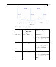
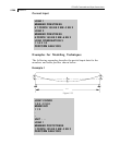
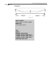
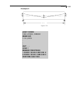
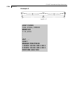
The following examples describe the partial input data for the
members and cable profiles shown below.
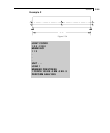
Example 1
3
3
3
10ft
Figure 5.33
JOINT COORD
1 0 0 ; 2 10 0
MEMB INCI
1 1 2
.
..
UNIT . . .
LOAD 1
MEMBER POSTSTRESS
1 FORCE 100 ES 3 EM -3 EE 3
PERFORM ANALYSIS


