STAAD Commands and Input Instructions
Section 5
5-70
also. For details on specifying sections from the American steel
tables, see Section 2.2.1 of this manual.
*
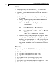
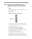
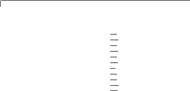
⎧SP f
1
⎫
⎪WP f
2
⎪
⎪TH f
3
⎪
⎪WT f
4
⎪
additional-spec =
⎨DT f
5
⎬
⎪OD f
6
⎪
⎪ID f
7
⎪
⎪CT f
8
⎪
⎪FC f
9
⎪
⎪CW f⎪
10
⎩
CD f
11
⎭
SP f
1
=
a. This set describes the spacing (f
1
) between angles or
channels if double angles or double channels are used.
f1 defaults to 0.0 if not given.
b. For composite sections, SP = rib height.
WP f
2
=
a. Width (f
2
) of the cover plate if a cover plate is used
with I shaped sections.
b. For composite sections, WP = bottom coverplate width.
TH f
3
=
a. Thickness (f
3
) of plates or tubes.
b. For composite sections, TH = bottom coverplate
thickness.
WT f
4
=
Width (f
4
) of tubes, where TUBE is the table-name.
DT f
5
=
Depth (f
5
) of tubes.
OD f
6
=
Outside diameter (f
6
) of pipes, where PIPE is the table-
name.
ID f
7
=
Inside diameter (f
7
) of pipes.
CT f
8
=
Concrete thickness (f
8
) for composite sections.
FC f
9
=
Compressive strength (f
9
) of the concrete for composite
sections.
CW f
10
=
Concrete width (f
10
) for composite sections.
CD f
11
=
Concrete density (f
11
) for composite sections. Default value
is 150 pounds/cu.ft.
See Section
1.7.2
Example
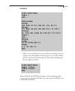
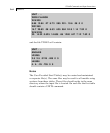
See Section 5.20.6


