Section 3
3-5
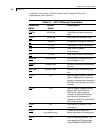
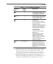
Table 3.1 – ACI 318 Design Parameters
Parameter Default Description
Name Value
DEPTH *YD Depth of concrete member. This
value defaults to YD as provided
under MEMBER PROPERTIES.
NSECTION *** 12 Number of equally-spaced sections
to be considered in finding critical
moments for beam design.
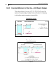
TRACK 0.0 BEAM DESIGN:
With TRACK set to 0.0, Critical
Moment will not be printed out with
beam design report.
A value of 1.0 will mean a print out.
A value of 2.0 will print out required
steel areas for all intermediate
sections specified by NSECTION.
COLUMN DESIGN:
TRACK 0.0 prints out detailed
design results.
TRACK 1.0 prints out column
interaction analysis results in
addition to TRACK 0.0 output.
TRACK 2.0 prints out a schematic
interaction diagram and
intermediate interaction values in
addition to all of above.
RHOMN 0.01 (indicates 1%) Minimum reinforcement (as the
fractional number) required in a
concrete column. Enter a value
between 0.0 and 0.08 where 0.08
stands for 8%, the max allowed by
the ACI code.
* These values must be provided in the current unit system being used.
** When using metric units for ACI design, provide values for these
parameters in actual 'mm' units instead of the bar number. The
following metric bar sizes are available: 6 mm, 8 mm, 10 mm, 12
mm, 16 mm, 20 mm, 25 mm, 32 mm, 40 mm, 50 mm and 60 mm.
*** NSECTION should have no member list since it applies to all
members. The minimum value allowed is 12, the maximum is 20. If
more than one NSECTION entered, then highest value is used.


