STAAD Commands and Input Instructions
Section 5
5-40
surface boundaries provided the nodes are collinear on edges
they belong to. In addition, the user specifies the number of
edge divisions that will be the basis for mesh generation. A
single command per wall is used for this purpose. The
program will subdivide all edges into the requested number
of fragments and each of these fragments will become an
edge of a plate element. However, if the original surface
edges have additional nodal points between the corners, all
node-to-node lengths of the surface edge will be divided into
the same number of fragments.
2. Surface thickness and material constants are specified in a
manner similar to that for plate elements, except that,
currently, only a constant surface thickness is supported.
3. A support generation function allows quick assignment of
support specifications to multiple nodal points.
4. Surface elements may be loaded by uniformly distributed
loads in any global direction or by loads normal to the plane.
5. It is possible to obtain in-plane bending moments as well as
stresses along any arbitrary line cutting the surface.
Example
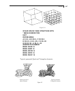
SET DIVISION 12
SURFACE INCIDENCES
2 5 37 34 SUR 1
34 37 54 51 SUR 2
19 16 65 68 SUR 3 DIV 10 16 10 16 –
RECO 5.8 1.5 6.9 6.4 1.5 6.9 6.4 0.5 6.9 5.8 0.5 6.9 DIV 5 10 5 10
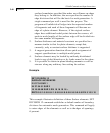
This example illustrates definition of three Surface elements. SET
DIVISION 12 command establishes a default number of boundary
divisions for automatic mesh generation. This command will apply
to outer edges of the elements as well as to the edges of openings,
if present.


