Section 5
5-157
words, the region should have the shape of a convex polygon. The
example below explains the method that may be used to get around a
situation where a convex polygon is not available.
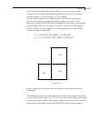
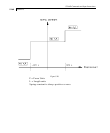
For the model comprised of plate elements 100 to 102 in the figure
below, one wishes to generate the spring supports at nodes 1 to 8.
However, a single ELASTIC MAT command will not suffice because the
internal angle between the edges 1-8 and 8-7 at node 8 is 270 degrees,
which violates the requirements of a convex polygon. So, one should
break it up into 2 commands:
1 2 3 8 ELASTIC MAT DIREC Y SUBG 200.
3 4 5 6 7 8 ELASTIC MAT DIREC Y SUBG 200.
101
102
100
8
7
6
1
5
2
4
3
Figure 5.19
Joints 3 and 8 will hence get the contribution from both of the above
commands.
The command works only when the plane of the closed region is parallel
to one of the global planes X-Y, Y-Z or X-Z. For regions that are inclined
to one of the global planes, the spring constant will have to be evaluated
manually and specified using the FIXED BUT type of spring support.


