


5 - 24 5 - 24
MELSOFT
5 UTILITY OPERATIONS
Item Description
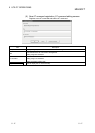
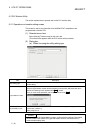
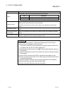
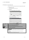
Set the order in which the bit devices being monitored are arranged.
Item Description
F-0 Arranged in order of F, E, ... 1, 0 from left to right.
0-F Arranged in order of 0, 1, ... E, F from left to right.
Bit order
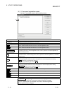
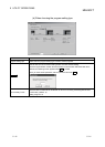
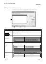
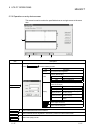
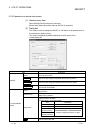
1) (Monitor screen)
Shows the device statuses.
Clicking the device name shows the device write screen.
For details of the device write screen, refer to "Section 5.2.5 Operations on device write
screen".
2) (Target CPU name)
Shows the communication target CPU name specified on the communication setting wizard
screen.
3) (Communication path
information)
Shows such information as the network type, network number, first I/O address and station
number.
4) (Logical station number)
Shows the logical station number set for the utility setting type.
This does not appear when the program setting type is used.
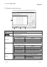
POINT
(1) For the bit device statuses, 1 indicates an ON status and 0 an OFF status.
(2) Bit devices are monitored in units of 16 points.
If any device outside the range supported by the programmable controller CPU
is included in the 16 points, its value is displayed "0".
(3) Specifying the device memory in the U
\G format enables the buffer memory to
be monitored.
(4) When monitoring the set values of the timers and counters, indirectly specify the
data registers.
(5) For the X and Y devices of the FXCPU, type their device numbers in octal.
(6) For the C devices of the FXCPU, C0 to C199 (16 bit) and C200 and later (32 bit)
are displayed separately.
(7) Devices cannot be monitored if the connection destination is not established.
(8) During monitoring, you cannot make transfer setting.
(9) During monitoring, "
" flickers under the scroll button.