


APP - 34 APP - 34
MELSOFT
A
PPENDICES
POINT
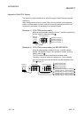
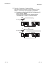
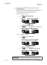
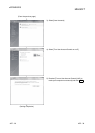
• Route switching is not executed if a communication error has already occurred at
a communication start for the Redundant CPU specified as the target.
(A communication error occurs.)
• In the case of Ethernet connection, it may take time from when a communication
error occurs until communication starts after connection to the control system.
• If a communication error has occurred, refer to (b) in (3) Automatic switching of
communication route, and remove the communication disturbance.
REMARK
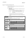
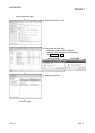
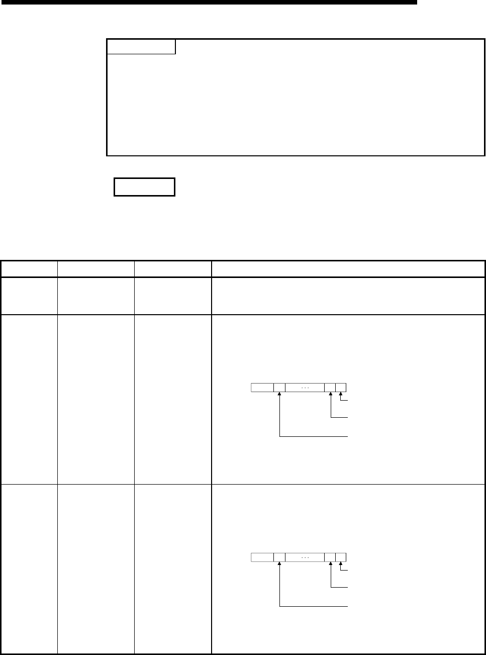
The following indicates details of the special relay and special registers to be
monitored when estimating whether route switching occurred or not.
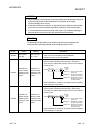
Number Name Meaning Explanation
SM1600
Other system
error flag
OFF: No error
ON: Error
• Turns on when an error occurs during redundant system error
check. (Turns on when either of bits for SD1600.)
• Remains off when no errors are present.
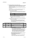
SD1590
Module No. for
network module
requesting route
switching in host
system
Module No. for
network module
requesting route
switching in host
system
• Any of the following bits turns on corresponding to module No. for
network module requesting route switching in host system.
• Turns off by the system after recovery from error of the relevant
module by user.
b1 b0b15 b11to to
to
0 0/1 00/1SD1590
0: OFF
1: ON
Bit status
Module No. 0: Invalid, as CPU module
uses 2 slots.
Module No. 1: Indicates the module to
the right of CPU module
Module No.11: Indicates the module at
the right end of a 12-I/O
slot base (Q312B)
• Refer to SD1690 for module No. for network module requesting
route switching in other system.
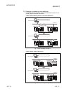
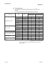
SD1690
Module No. for
network module
requesting route
switching in other
system
Module No. for
network module
requesting route
switching in other
system
• Any of the following bits turns on corresponding to module No. for
network module requesting route switching in other system.
• Turns off by the system after recovery from error of the relevant
module by user.
b1 b0b15 b11to to
to
0 0/1 00/1SD1690
0: OFF
1: ON
Bit status
Module No. 0: Invalid, as CPU module
uses 2 slots.
Module No. 1: Indicates the module to
the right of CPU module
Module No.11: Indicates the module at
the right end of a 12-I/O
slot base (Q312B)
• Refer to SD1590 for module No. for network module requesting
route switching in host system.