6 - 101 6 - 101
MELSOFT
6 COMMUNICATION SETTING EXAMPLES OF THE UTILITY SETTING TYPE
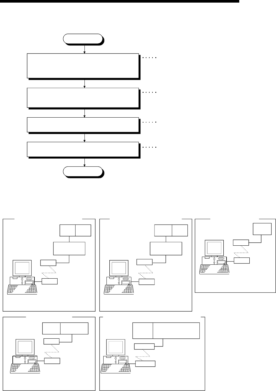
Start
When using the QC24N, set the mode setting and
transmission setting switches.
When using the Q series-compatible C24,
L series-compatible C24 set the software switches.
Start the communication setup utility and make
setting on the communication setting wizard.
On the communication test screen, check whether
communication can be made properly. *1
End
In the sequence program, set the following items.
1) Write the AT command (ATS0=1).
2) Set the initialization request.
<When QC24N or Q series-compatible C24, L series-compatible C24 is used>
Refer to Section 6.17.2 (2).
Refer to Section 6.17.2 (4).
Refer to Section 6.17.2 (5).
Refer to Section 6.17.2 (6).
*1: If normal communication cannot be made, refer to
"Appendix 6 Flowchart for the Case Where Access
Cannot Be Made during Modem Communication"
and take corrective action.
(1) System example
The following system example is used in this section.
IBM-PC/AT compatible
(MX Component)
COM1 is used.
Q2ACPU
QC24N
(Station No. 0)
<When QC24N is used>
modem 2)
modem 1)
IBM-PC/AT compatible
(MX Component)
COM1 is used.
Q25HCPU
Q series-compatible C24
L series-compatible C24
(Station No. 0)
<Q series-compatible C24, L series-compatible C24>
"13" is used as logical
station number.
Pushbutton dialing line (tone)
modem
IBM-PC/AT compatible
(MX Component)
COM1 is used.
A2USH
CPU-S1
A6TEL,
Q6TEL (A mode)
modem
<When A6TEL or Q6TEL is used>
IBM-PC/AT compatible
(MX Component)
COM1 is used.
Q2ACPU
Q6TEL
(QnA mode)
<When Q6TEL (QnA mode) is used>
IBM-PC/AT compatible
(MX Component)
COM1 is used.
FX
2NC
<When FXCPU is used>
modem
modem
modem
modem
modem
modem


