6 - 1 6 - 1
MELSOFT
6 COMMUNICATION SETTING EXAMPLES OF THE UTILITY SETTING TYPE
6 COMMUNICATION SETTING EXAMPLES OF THE UTILITY SETTING TYPE
This chapter explains the setting procedure and setting example of each
communication path when the utility setting type is used for programming.
POINT
• For the settings other than “As set by user”, set the value as shown in the table.
• Before attempting to communicate with MX Component for the first time, check if
MX Component can communicate normally using GX Developer. It will help
detecting errors when MX Component cannot communicate with the CPU
module.
• For details of the settings for the module, refer to the manual of each module.
6.1 Computer Link Communication
This section provides the computer link communication procedure and its setting
example using the utility setting type.
6.1.1 Settings of computer link modules
This section gives the switch settings of computer link modules for the use of MX
Component.
The settings of MX Component should be the same as the module.
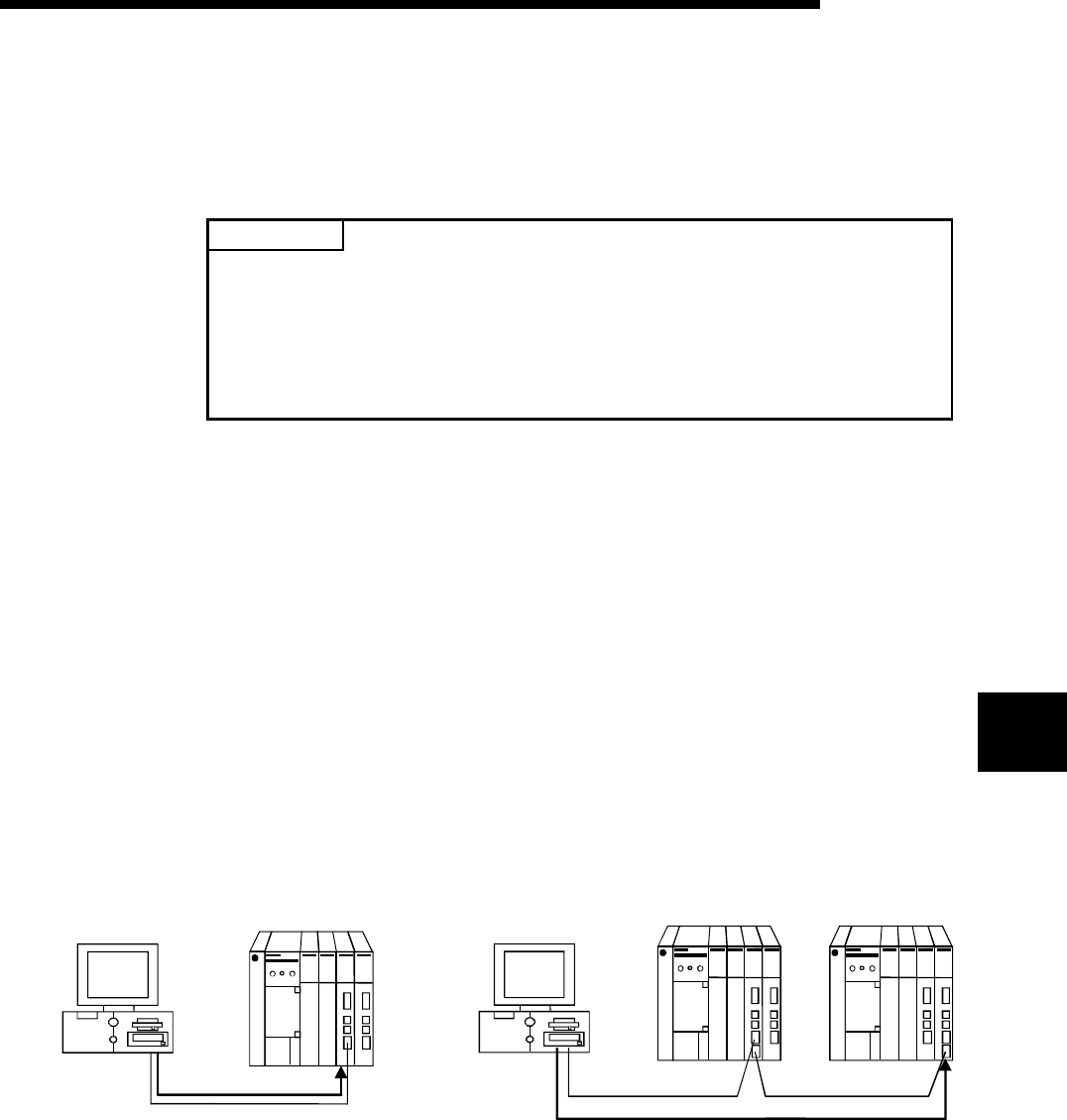
The following figures are used to explain each module.
<When using C24, UC24, QC24(N), Q series compatible C24 or L series compatible C24>
(For 1:1 communication)
IBM-PC/AT
compatible
(For 1:n communication)
Station 0 *2 Station 1
*2: Limited for use of both CH1 and CH2
IBM-PC/AT Station 0
compatible
*1: Limited for use of only CH1
*1
6


