6 - 9 6 - 9
MELSOFT
6 COMMUNICATION SETTING EXAMPLES OF THE UTILITY SETTING TYPE
6.1.2 Accessing procedure
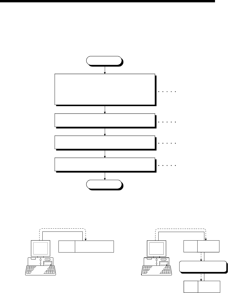
The procedure for making access to the programmable controller CPU using computer
link communication will be explained in the following order.
START
When using the C24, UC24 or QC24(N), set the
mode and transmission setting switches.
When using the Q series-compatible C24, set the
software switches.
When using the FX extended port, set the PLC
parameters.
Connect the computer link module and IBM-PC/AT
compatible.
Start the communication setup utility and make
setting on the communication setting wizard.
On the communication test screen, check whether
communication can be made properly.
END
Refer to Section 6.1.2 (2).
Refer to Chapter 2.
Refer to Section 6.1.2 (3).
Refer to Section 6.1.2 (4).
(1) System examples
The following system examples are used in this section.
Q2A
CPU
Q2A
CPU
Logical station number o
f
"1" is used.
<For 1:1 communication> <For 1:n communication>
IBM-PC/AT compatible
(MX Component) COM1
is used.
Q25H
CPU
Q series-compatible
C24 (Sta. No.1)
IBM-PC/AT compatible
(MX Component) COM1
is used.
Module 1)
QC24
(Sta. No.1)
QC24
(Sta. No.3)
Module 2)
Computer link (Multidrop
communication)


