


6 - 52 6 - 52
MELSOFT
6 COMMUNICATION SETTING EXAMPLES OF THE UTILITY SETTING TYPE
6.8 CC-Link Communication
This section provides the CC-Link communication procedure and its setting example
using the utility setting type.
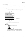
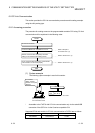
6.8.1 Accessing procedure
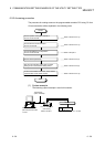
The procedure for making access to the programmable controller CPU using CC-Link
communication will be explained in the following order.
START
Set the CC-Link board.
Connect the IBM-PC/AT compatible to CC-Link.
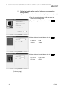
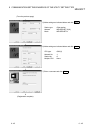
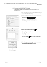
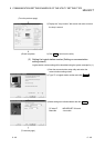
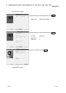
Start the communication setup utility and make
setting on the communication setting wizard.
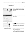
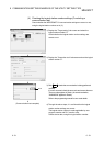
On the communication test screen, check whether
communication can be made properly.
END
Refer to Chapter 2
and Section 6.8.1 (2).
Refer to Section 6.8.1 (3).
Refer to Section 6.8.1 (4).
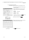
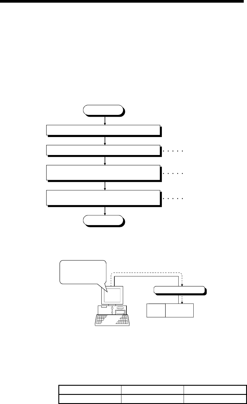
(1) System example
The following system example is used in this section.
CC-Link
Logical station number of "6" is used.
Local station
Station number 1
Number of occupied
stations 4
IBM-PC/AT compatible
(MX Component) First
CC-Link board is used.
Transmission speed: 10Mbps
Q02H
CPU
Local station
(Sta. No.5)
* Accessible to the FXCPU with CC-Link communication only via the serial/USB
connection of the QCPU or via the Q series-compatible C24.
Supported CPUs and module in CC-Link communication to FXCPU are as follows.
CC-Link module Compatible CPU Station number
FX3U-64CCL FX3G,FX3U(C) 1 to 63