


2 - 14 2 - 14
MELSOFT
2 SYSTEM CONFIGURATIONS
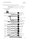
(c) Switch settings of the computer link module
For the switch settings for the use of MX Component, refer to "Section 6.1.1
Switch settings of computer link modules".
(d) Cable for connection
For the connection cable, refer to the manual of your computer link module.
Refer to Appendix 3 for cable pin assignment.
POINT
Only the RS-232 connector may be used for connection of the IBM-PC/AT
compatible and computer link (serial communication) module.
The RS-422 connector or RS-422/485 terminal block cannot be used.
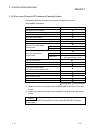
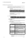
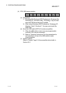
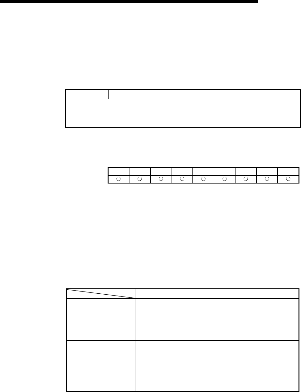
(2) Ethernet communication
1) In case of using Ethernet interface modules
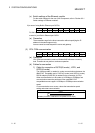
NT 95 98 2000 Me XP Vista 7(32) 7(64)
For the way to make connection to the Ethernet module, refer to the manual of
your Ethernet module.
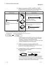
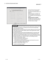
(a) Precaution
The accessible range for Ethernet communication is the same segment only.
Access cannot be made beyond the router and gateway.
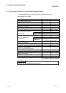
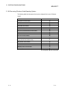
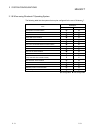
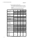
(b) Usable modules
Any of the following Ethernet modules may be used to access the
programmable controller CPU.
For the FX series Ethernet module, refer to the user’s manuals for the FX
series.
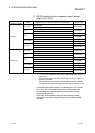
Usable Modules
E71 *1
AJ71E71, AJ71E71-S3, A1SJ71E71-B2, A1SJ71E71-B5,
A1SJ71E71B2-S3, A1SJ71E71B5-S3, AJ71E71N-T,
AJ71E71N-B5, AJ71E71N-B2, AJ71E71N-B5T, AJ71E71N3-T,
A1SJ71E71N-T, A1SJ71E71N3-T, A1SJ71E71N-B5,
A1SJ71E71N-B2, A1SJ71E71N-B5T
QE71 *2
AJ71QE71, AJ71QE71-B5, A1SJ71QE71-B2, A1SJ71QE71-B5,
AJ71QE71N-T, AJ71QE71N-B5, AJ71QE71N-B2,
AJ71QE71N3-T, AJ71QE71N-B5T, A1SJ71QE71N-T,
A1SJ71QE71N3-T, A1SJ71QE71N-B5, A1SJ71QE71N-B2,
A1SJ71QE71N-B5T
Q series-compatible E71 QJ71E71, QJ71E71-B2, QJ71E71-B5, QJ71E71-100
*1: Accessible as equivalent to the AnACPU when fitted to the AnUCPU.
*2: An error will occur if monitoring via QnA Ethernet and monitoring via
other communication path are executed for the same CPU
simultaneously.