


17. 16 MHz PLL Adjustment
17. 16 MHz PLL Adjustment
Assembly
Adjusted
A2 controller assembly
Related
Performance
Tests
Sweep Time Accuracy
Gate Delay Accuracy and Gate Length Accuracy
Delayed Sweep Accuracy
Fast Sweep Time Accuracy (Option 007)
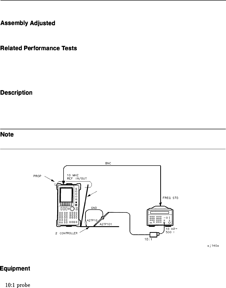
Description
The 16 MHz CPU clock is phase locked to the 10 MHz reference. The output of the 16 MHz
PLL loop integrator is adjusted for a clock frequency of approximately 14.4 MHz with the
loop unlocked. This ensures that the CPU will still function and the display annotation will
be distorted but readable, even if the 10 MHz reference to A2 is absent.
Note
If necessary, perform the display adjustments after performing the following
adjustment.
BNC
CABLE
f
PC BOARD
PRoP
\
-
%%,O”T
\
w
FREQ
STD
OUT
r
A3 INTERFACE
SPECTRUM
ANALYZER
A
FREQUENCY
COUNTER
z-
MHZ
1O:I PROBE
sjl40e
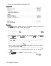
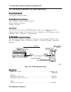
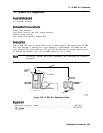
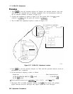
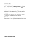
Figure 2-26. 16 MHz PLL Adjustment Setup
Equipment
Microwave frequency counter
. . . . . . . . . . . . . . . . . . . . . . . . . . . . . . . . . . . . . HP 5343A
10:lprobe
. . . . . . . . . . . . . . . . . . . . . . . . . . . . . . . . . . . . . . . . . . . . . . . . . . . . . HP 10432A
Adjustment Procedures 2-63