


Center frequency
. . . . . . . . . . . . . . . . . . . . . . . . . . . . . . . . . . . . . . . . . . . .
..300MHz
Span
. . . . . . . . . . . . . . . . . . . . . . . . . . . . . . . . . . . . . . . . . . . . . . . . . . . . . . . . . . . . OHz
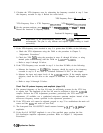
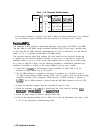
29. Connect an RF signal-generator output to A14J501. Set the signal generator to the
following settings:
Frequency
. . . . . . . . . . . . . . . . . . . . . . . . . . . . . . . . . . . . . . . . . . . . . . . . . . .
..56MHz
Amplitude
. . . . . . . . . . . . . . . . . . . . . . . . . . . . . . . . . . . . . . . . . . . . . . . . . . . .
..OdBm
30. Monitor A14J17 pin 1 with a DVM or oscilloscope. Connect ground to A14J17 pin 6.
31. As the signal generator frequency is increased to 76 MHz, the voltage at A14J17 pin 1
should change from approximately
+12
V to -12 V.
32. Set the signal generator to the following settings and repeat step 30.
Frequency
. . . . . . . . . . . . . . . . . . . . . . . . . . . . . . . . . . . . . . . . . . . . . . . . . . .
..56MHz
Amplitude
. . . . . . . . . . . . . . . . . . . . . . . . . . . . . . . . . . . . . . . . . . . . . . . . . . . -15dBm
33. If the voltage monitored in step 30 is correct with a 0
dBm
output but not with -15
dBm
output, suspect the limiting amplifier function block AE.
34. Place jumper A14J23 in the NORMAL position and reconnect W32 to A14J501.
Check YTO FM coil driver and main loop error voltage driver (steps 35-40)
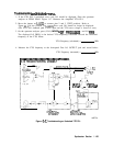
35. To troubleshoot the YTO FM coil driver, refer to step 6 of “first LO Span Problems
(2.01 MHz to 20 MHz).”
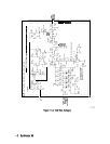
36. Steps 36 through 40 verify that the YTO-loop error voltage is reaching the FM coil.
The main loop error voltage driver has a gain of either 1.5 or 15; the analyzer firmware
controls the gain during the locking process. The error voltage is read by the ADC on the
A3 interface assembly. U324D calibrates out any offsets from true ground. A14U326A
inverts the sense of the YTO loop to lock the YTO on lower sampler-sidebands (YTO
frequency < (sampler frequency
x
sampler harmonic)). The fractional N frequency
indicated in the FREQ DIAGNOSE
menu will be negative when locking to lower
sidebands. Refer to function blocks E, M, and N of Al4 frequency control schematic in
the HP 8560 E-Series Spectrum Analyzers Component Level Information binder.
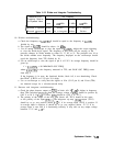
Set the spectrum analyzer to the following settings:
Center frequency
. . . . . . . . . . . . . . . . . . . . . . . . . . . . . . . . . . . . . . . . . . . .
..300MHz
Span
. . . . . . . . . . . . . . . . . . . . . . . . . . . . . . . . . . . . . . . . . . . . . . . . . . . . . . . . . . . . OHz
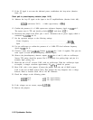
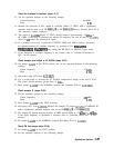
37. Remove jumper A14J23 and connect a dc power supply to A14J23 pin 2. Connect ground
to A14J23 pin 3. Set the dc power supply to
i-7.5
Vdc.
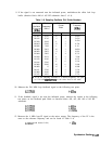
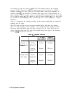
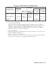
38. Verify the nominal test-point voltages listed in Table 11-8.
39. Change the input voltage to -7.5 volts and re-verify that the voltages listed in Table 11-8
are the same except for a change in polarity.
40. Change the
CEPJTER
FREq
to 678.8 MHz with the SPAN remaining 0 Hz. This will change
the switch setting of U326A and invert the voltages listed in Table 11-8.
11-28 Synthesizer Section