


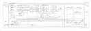
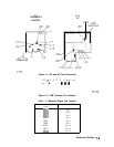
Frequency Counter
See function block Z of A2 schematic diagram (sheet 4 of 4) in the HP 8560 E-Series Spectrum
Analyzer Component Level Information.
The frequency counter counts the frequency of the last IF and provides accurate timing signals
for digital zero-spans. The circuit also provides timing signals to the A3 interface assembly
ADC (analog to digital converter). The nominal input frequency is 5.35 MHz (10.7 MHz
divided by 2). The circuit frequency reference in the frequency count mode is the 10 MHz
reference from the Al5 RF assembly. The frequency reference in digitized zero spans (sweep
times
230
ms) is the 4 MHz HPIB-CLK, selected by MUX
U704.
In the frequency count mode,
U702
prescales the 10 MHz reference by 5 to generate a 2 MHz
timebase. This
timebase
feeds through MUX
U704
to programmable-timer
U700
CLK2
input. Programmable-timer
U700
output (OUT2) is the gating signal (HBKT-PULSE)
for performing the frequency count. The gating time interval is a function of the counter
resolution which may be set between 10 Hz and 1 MHz. Table
10-2
lists the gate time for each
setting of COUNTER RES. The gate time is the period during which U511 pin 3 is high.
The FREQ COUNT input,
A2J7,
is gated in
U511B
by HBKT-PULSE. The gated signal
clocks divide-by-16 counters U703A and U703B. These counters are cascaded to form a
divide-by-256 counter. The MSB of this counter, CD7, clocks the CLKO input of
U700.
The
frequency of CD7 is a function of COUNTER RES as shown in Table 10-2. If timer
U700
overflows, OUT0 will be set and U701B clocked, generating CNTOVFLIRQ, which will
interrupt the CPU.
If
IRQAK2
is high, HBKT-PULSE will clock U701A, generating FREQCNTLIRQ. Upon
receiving the FREQCNTLIRQ interrupt, the CPU latches the CD0 to CD7 onto the BID
bus by setting LCDRD
(1
ow counter data read) low and reading the counter data from the
BID bus. The CPU will also read the data from the timer, U700, by setting L8254CS and
LCNTLRD low, placing the timer data on the BID bus. The CPU resets U701A by setting
IRQAK2 low via the BID bus and latch
U506.
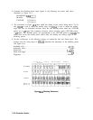
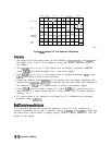
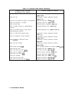
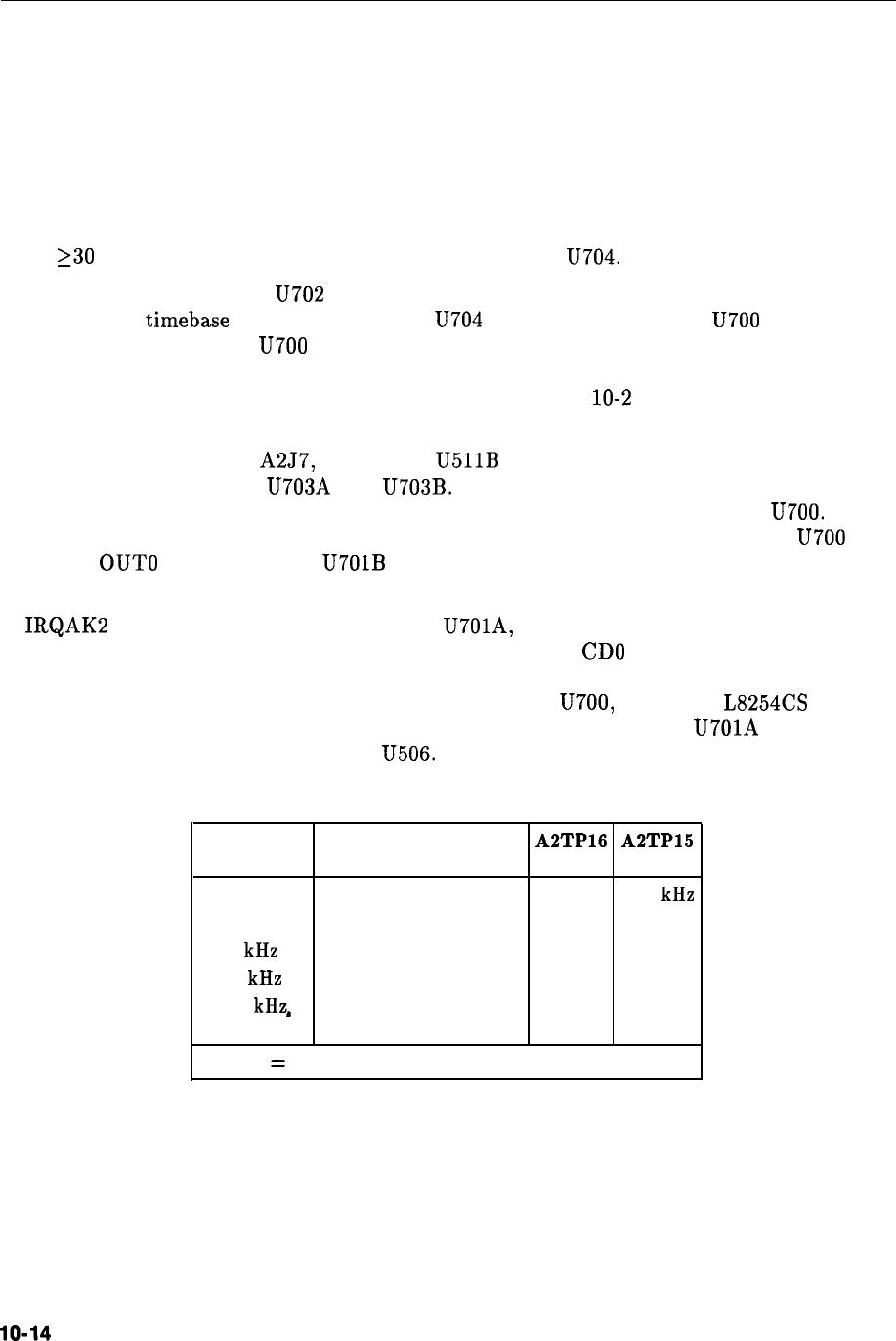
Table 10-2. Gate Times
Counter Res Gate Time* A2TP16
A2TP15
(U511 pin 3 high state)
10 Hz
200
ms
2 MHz 4.18 kHz
100 Hz 20 ms 2 MHz
418 Hz
1 kHz 2 ms 2 MHz 41.8 Hz
10 kHz 2 ms 2 MHz 41.8 Hz
100 kHz,
2 ms 2 MHz 41.8 Hz
1 MHz 2 ms 2 MHz 41.8 Hz
* TP15
=
(FREQ COUNT input x Gate Time)/256
lo-14
Controller Section