


Procedure 5. A2, A3, A4, and A5 Assemblies
Procedure 5.
A2, A3, A4, and A5 Assemblies
Removal
1. Remove the spectrum analyzer cover.
2. Place the spectrum analyzer on its right side frame.
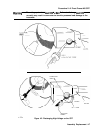
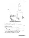
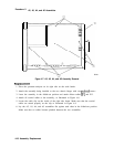
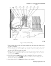
3. Remove the eight screws holding the A2, A3, A4, and A5 assemblies to the top of the
spectrum analyzer. These screws are labeled
(2),
(3),
and (4) in Figure 4-7. They are also
labeled on the back of the A2 board assembly.
4. Remove ribbon cable W4 from A2J6. See Figure 4-7.
Caution
Do not fold the board assemblies out of the spectrum analyzer one at a time.
Always fold the A2 and A3 assemblies as a unit and the A4 and A5 assemblies
as a unit. Folding out one assembly at a time binds the hinges attaching the
assemblies and may damage an assembly and hinge.
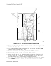
5. The board assemblies are attached to the right side frame of the spectrum analyzer with
two hinges. Fold both the A2 and A3 assemblies out of the spectrum analyzer as a unit.
6. Fold both the A4 and A5 assemblies out of the spectrum analyzer as a unit.
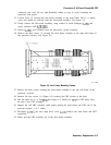
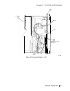
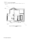
7. Remove the cables from the assembly being removed, as illustrated in Figure 4-8.
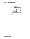
8. Remove the two screws that attach the assembly being removed to its two mounting hinges.
Caution
Do not torque shield TORX screws to more than 8 inch-pounds. Applying
excessive torque will cause the screws to stretch.
Assembly Replacement
4-
15