


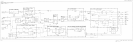
A5 IF Assembly
The A5 IF assembly has four crystal filter poles, four LC filter poles, and step gain amplifiers.
The crystal filters provide resolution bandwidths of 300 Hz to 10 kHz. The LC filters provide
resolution bandwidths of 30 kHz to 2 MHz. All filter stages are in series. PIN diode switches
bypass unwanted stages.
An automatic IF adjustment, in spectrum analyzer firmware, sets center frequency and 3 dB
bandwidth of all filter poles through varactor and PIN diodes. The firmware also controls
crystal-pole symmetry and the step gain amplification.
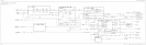
ADC/lnterface
Section
The ADC/interface section is the link between the controller section and the rest of the
spectrum analyzer. It controls the RF, synthesizer,and IF sections through address and data
lines on the W2 control cable (analog bus). Analog signals from these sections are monitored
by the ADC/interface section ADC (analog to digital converter) circuit.
The ADC/interface section includes the A3 interface assembly,
AlAl
keyboard, and
AlA
RPG (front-panel knob). The A3 assembly includes log expand, video filter, peak detector,
track-and-hold, real-time DACs, RF gain DACs,
+lO
V reference, and ADC circuitry. The
digital section of the assembly includes ADC ASM, sweep trigger, keyboard interface, RPG
interface, and analog bus interface circuitry.
ADC
The spectrum analyzer can digitize signals with either the main ADC on the A3 interface
assembly, or the optional Al6 fast ADC (Option 007). The main ADC is used for digitizing
video signals (when the sweep time is
230
ms) and various other signals such as PLL error
voltages. The fast ADC is used only to digitize video signals for sweep times
530
ms.
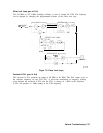
Main ADC (part of A3 interface assembly). For slower sweep times
(130
ms), the spectrum
analyzer uses a successive-approximation type of ADC. The main ADC has a
lo-bit
resolution
but it is realized with
la-bit
hardware. The ADC algorithmic state machine (ADC ASM)
controls the interface between the start/stop control and the ADC itself, switching between
positive and negative peak detectors when the NORMAL detector mode is selected, and
switching the ramp counter into the ADC for comparison to the analog sweep ramp.
Fast ADC. When Option 007 is installed and sweep times
530
ms are selected, the spectrum
analyzer digitizes video signals with the Al6 fast ADC. The fast ADC uses an
&bit
flash
ADC, sampled at a 12 MHz rate. Only POS PEAK, NEG PEAK, and SAMPLE detector
modes are available with fast ADC; NORMAL detector mode is not available. Pretriggering is
possible with fast ADC.
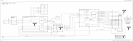
Log Expand/Video Functions
The A3 interface assembly performs log expand and offset functions. The log expand/log
offset amplifier provides a 2 dB/Div log scale. When the main ADC is used, the 5 dB/Div
scale is derived by multiplying the digitized 10 dB/Div trace data by two in the CPU. When
the fast ADC is used, the 5 dB/Div scale is derived by amplifying the video signal by two.
The 1 dB/Div scale is similarly derived by either multiplying the 2 dB/Div trace data by two
(main ADC) or amplifying the video signal by two (fast ADC).
The spectrum analyzer uses two types of video filters. An RC low-pass circuit provides 300 Hz
to 3 MHz video bandwidths. Video bandwidths
5100
Hz are generated using digital filtering.
General Troubleshooting 7-49