


Procedure 2. Al Front Frame/Al8 CRT
(4 PLACES)
1
0
v
0
-0
2
ENEATH CABLES)
SI
12e
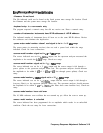
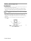
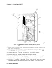
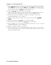
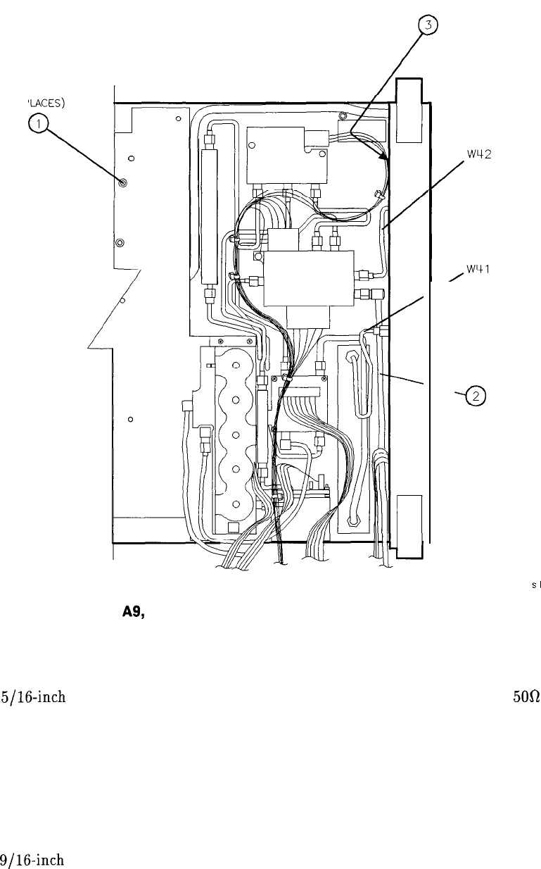
Figure 4-3. A9, A18, and Line-Switch Assembly Mounting Screws
17. Remove screw (2)
securing the A9 input attenuator assembly to the center support on the
front frame. See Figure 4-3.
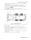
18. Use a
5/16-inch
open-end wrench to disconnect W41 from the front panel INPUT
500
connector. Loosen the opposite end of W41.
19. Disconnect W42 from A7 and the front panel First LO OUTPUT connector.
20. Disconnect W36, coax 86, from the front panel IF INPUT connector.
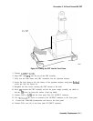
21. Remove the VOLUME knob and potentiometer from the front panel. If necessary, drill
out the nut driver used to remove the VOLUME potentiometer and cover the tip with
heatshrink tubing or tape to avoid scratching the enameled front panel.
22. Use a
9/16-inch
nut driver to remove the dress nut holding the front panel CAL OUTPUT
connector to the front panel. If necessary, drill out the nut driver to fit over the BNC
4-8 Assembly Replacement