


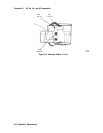
Procedure 6. A6 Power Supply Assembly
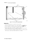
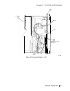
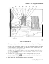
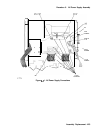
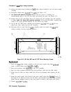
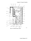
15. Disconnect all cables from the A6 power supply assembly. See Figure 4-11.
16. Use a TORX screwdriver to remove the hardware from the shield wall, the heatsink, and
the A6 power supply assembly.
17. Remove the A6 power supply assembly by lifting from the regulator
heatsink
toward front
of spectrum analyzer.
Replacement
1. Ensure that the bottom shield wall is in place before replacing the A6 power supply
assembly.
2. Attach the A6 power supply assembly to the spectrum analyzer chassis and top shield wall
using the four screws.
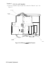
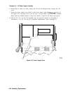
3. Connect
Wl
to
A6J1,
W3 to
A6J2,
fan power wires to
A6J3,
W8 to
A6J4,
and the
line-power jack to
A6JlOl.
See Figure 4-11.
4. Secure the
A6Al
high voltage assembly to the A6 power supply assembly, using three
TORX screws. Connect ribbon cable
A6AlWl
to
A6J5.
5..
Snap post-accelerator cable
A6AlW3
to the CRT assembly.
4-22 Assembly Replacement