


Phase Noise Problems
System phase noise can be a result of noise generated in many different areas of the spectrum
analyzer. When the spectrum analyzer is functioning correctly, the noise can be observed as a
function of the distance away (the offset) from the carrier frequency. The major contributor
to system noise can be characterized as coming from specific circuit areas depending upon the
offset frequency.
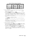
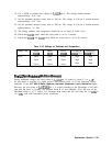
Some very general recommendations can be made for identifying which circuitry is the cause
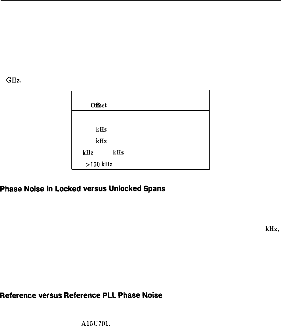
of the noise at certain offsets. The recommendations below apply with a center frequency of
1 GHz.
Carrier Frequency
Major Contributor
Of&et
(when working correctly)
100 Hz
1
kHz
3
kHz
10
kHz
to 150
kHz
>150
kHz
Reference (OCXO or TCXO)
600 MHz reference PLL
Fractional N PLL
Offset lock loop or YTO loop
YTO
Phase
Noise
in
Locked
versus
Unlocked
Spans
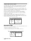
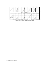
Input a signal to the spectrum analyzer. Set the center frequency to the input signal
frequency, set the span to 2 MHz, and plot the display. This plots the system noise for a
locked sweep. Plot the display again with a span of 2.01 MHz (lock and roll sweep).
The crossover point of the noise floor of the two plots is typically at an offset of about 50
kHz,
for a functioning instrument.
If the crossover point is shifted out to a higher offset frequency, suspect the YTO loop
circuitry.
If the crossover point is shifted in to a lower offset frequency, suspect the offset or fractional N
loop circuitry.
Reference
versus
Reference
PLL
Phase
Noise
If the problem seems to be in the frequency reference or reference PLL circuitry, measure the
noise with internal and external references. If there is no difference, suspect the circuitry
associated with the SAWR A15U701.
Synthesizer Section 11-43