


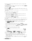
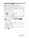
15. Press
m
to turn spectrum analyzer off.
16. Reconnect
AlAlWl
to A3J602 and remove all jumpers.
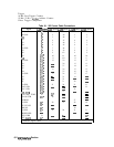
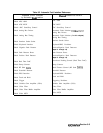
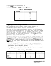
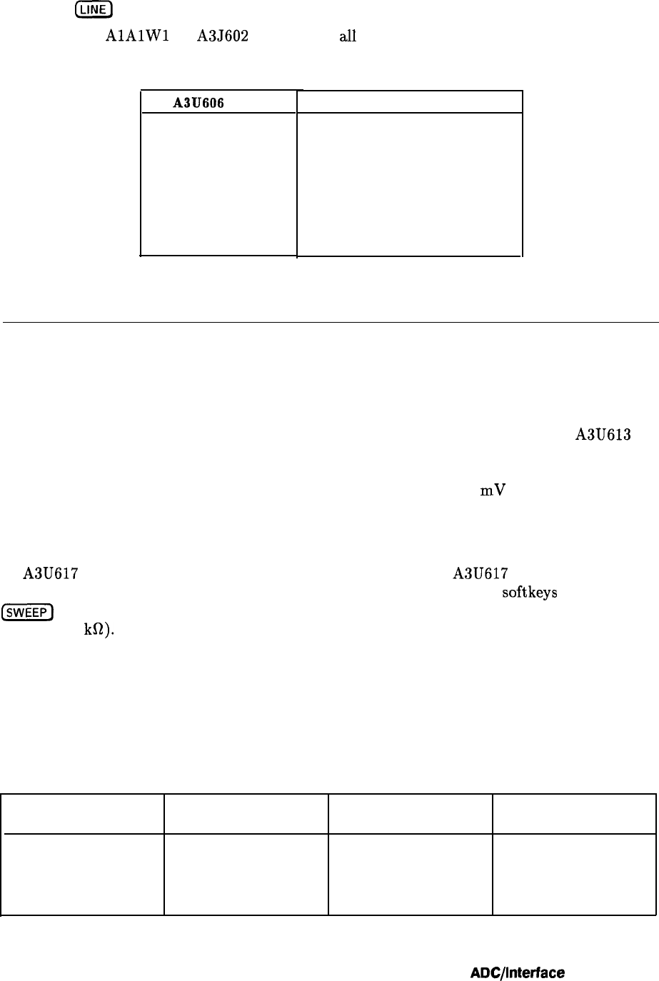
Table 8-5. Counter Frequencies
A3U606
pin #
Nominal Frequency (Hz)
3
3900
4
1950
5
975
6
488
11
244
10
122
9
61
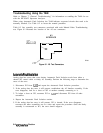
Triggering or Video Gating Problems
Refer to function block H of A3 Interface Assembly Schematic Diagram in the
HP 8560 E-Series Spectrum Analyzer Component Level Information.
The 1 MHz ADC clock provides synchronization in FREE RUN and SINGLE triggering.
LINE triggering synchronization originates on the A6 power supply. Trigger MUX A3U613
selects between FREE RUN, VIDEO, LINE, and EXTERNAL trigger sources. The trigger
signal sets the output of the HSCAN latch high. HBADC-CLKO provides the trigger
signal for FREE RUN. The VIDEO TRIG signal must be at least 25
mV
(0.25 divisions)
peak-to-peak to trigger in video trigger mode.
The trigger for Gated Video has two modes of operation, level mode and edge mode. In the
edge mode, positive-edge or negative-edge triggering can be selected. Output 0 from pin 10
of A3U617 generates the gate delay and output 1 from pin 13 of A3U617 generates the gate
length. The duration of these two time intervals is set using front-panel softkeys under the
(%@Z]
key. The trigger input for Gated Video is the rear-panel EXT/GATE TRIG INPUT
(TTL > 10
kR).
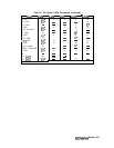
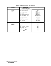
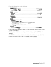
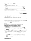
1. Check that the trigger MUX is receiving the proper trigger source information by
selecting each of the following trigger modes and checking the TRIG-SOURCE0 and
TRIG-SOURCE1 lines as indicated in Table 8-6.
2. If a trigger mode does not work, check that a trigger signal is present at the appropriate
trigger MUX input, as indicated in the table.
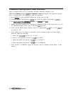
Table 8-8. Trigger MUX Truth Table
Trigger Mode
FREE RUN
VIDEO
LINE
EXTERNAL
TRIG-SOURCE0
TRIG-SOURCE1
U613 pin 14
U613 pin 2
L
L
H
L
H H
L H
MUX Input
Pin Number U613
6
5
3
4
ADC/lnterface
Section 8-9