


YTO
Main
Coil
Span
Problems
(LO
Spans
>20
MHz)
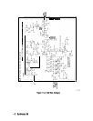
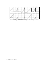
For YTO main coil spans, the YTO is locked at the beginning of the sweep and the sweep
ramp is summed into the main coil tune driver.
1. Perform the YTO adjustment procedure in Chapter 2, “Adjustment Procedures.” If the
YTO adjustments cannot be performed, continue with step 2.
2. Set the spectrum analyzer to the following settings:
Start frequency . . . . . . . . . . . . . . . . . . . . . . . . . . . . . . . . . . . . . . . . . . . . . . . .
..lOMHz
Stop frequency . . . . . . . . . . . . . . . . . . . . . . . . . . . . . . . . . . . . . . . . . . . . . . . . . 2.9 GHz
3. Verify that a
-1.2 V to -4.8 V ramp (approximately) is present at A14U331 pin 2.
4. If this ramp is not present, troubleshoot the main/FM sweep switch. See function block H
of Al4 frequency control schematic.
5. Measure the output of the main coil tune DAC at A14J18 pin 3. At the frequency settings
of step 2, this should be -2.48 V. If the voltage is not -2.48 V, troubleshoot the main coil
tune DAC. See function block E of Al4 frequency control schematic.
YTO
FM
Coil
Span
Problems
(LO
Spans
2.01
MHz
to
20
MHz)
In YTO FM coil spans, the YTO loop is locked and then opened while the sweep ramp is
summed into the FM coil. The FM coil sensitivity is corrected by changing the sensitivity of
the FM coil driver.
1. Perform the YTO Adjustment procedure in Chapter 2, “Adjustment Procedures.” If the
YTO adjustments cannot be performed, continue with this procedure.
2. Set the spectrum analyzer to the following settings:
Center frequency . . . . . . . . . . . . . . . . . . . . . . . . . . . . . . . . . . . . . . . . . . . . .
..300MHz
Span . . . . . . . . . . . . . . . . . . . . . . . . . . . . . . . . . . . . . . . . . . . . . . . . . . . . . . . . .
..20MHz
Sweep time . . . . . . . . . . . . . . . . . . . . . . . . . . . . . . . . . . . . . . . . . . . . . . . . . . . . . . 50ms
3. Check for the presence of a 0 V to -10 V sweep ramp at A14J15 pin 14 (input to the
main/FM sweep switch). Refer to function block H of Al4 frequency control schematic.
4. Check for the presence of a 0 V to
+5
V sweep ramp at A14U405 pin 6 (YTO FM coil
driver). Refer to function block M of Al4 frequency control schematic.
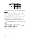
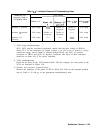
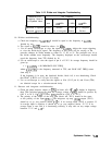
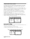
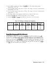
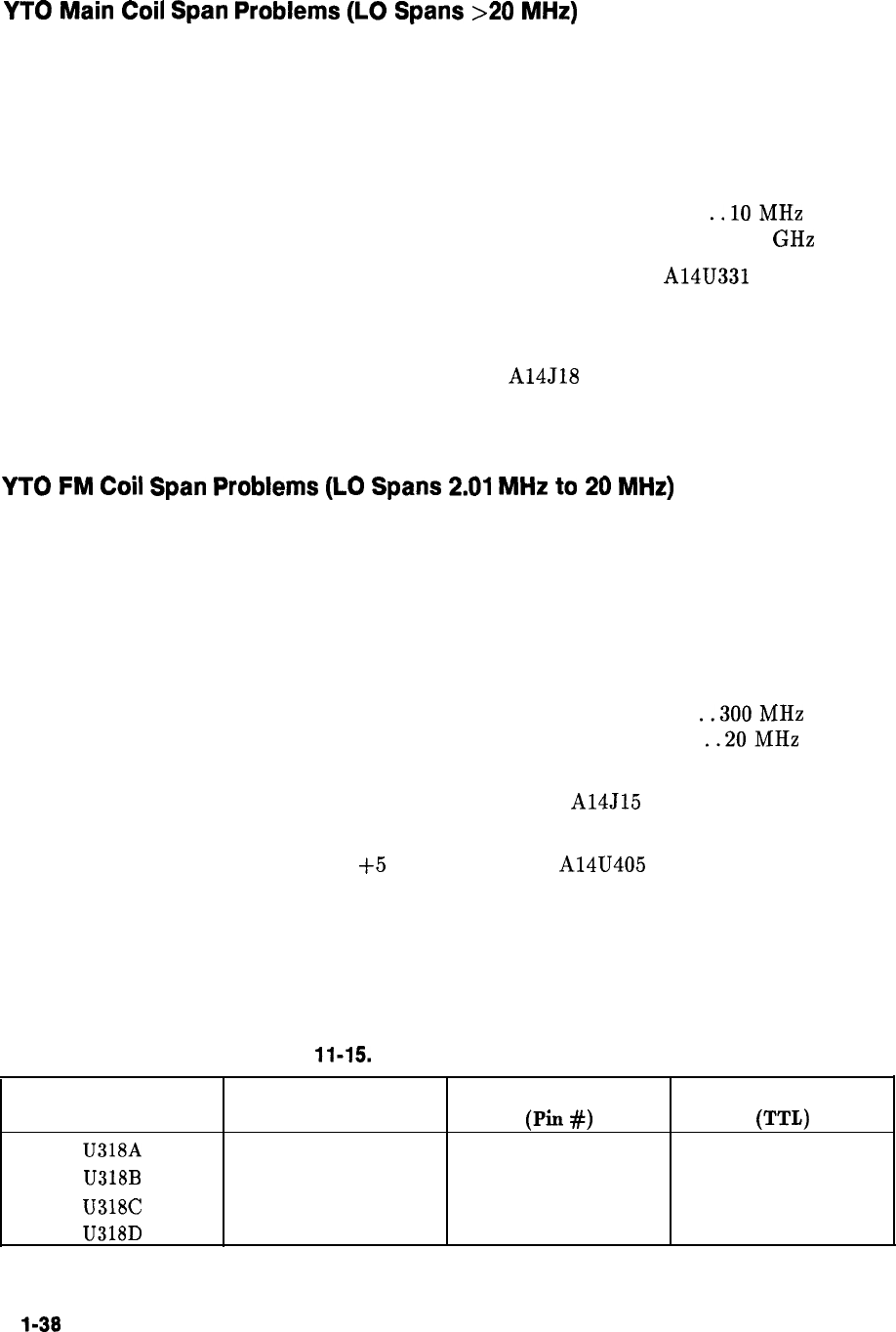
5. Check the state of the Main/FM sweep switches as indicated in Table 11-15.
6. The rest of the procedure troubleshoots the YTO FM coil driver.
Refer to function block M of Al4 frequency control schematic.
Table 11-15. Settings of Sweep Switches
Switch
Switch State
U318A
Closed
U318B
Open
U318C
Closed
U318D
Open
Switch Control Line
(Pin
#I
1
8
9
16
Control Line State
(TTL)
High
Low
Low
High
1
l-38
Synthesizer Section