


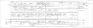
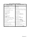
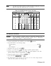
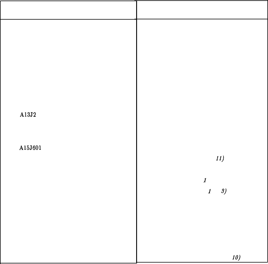
Table 12-1. Automatic Fault Isolation References
Suspected Circuit Indicated
by Automatic Fault Isolation
Check 2nd IF Amplifier
Check 2nd IF Distribution
Check 10.7 MHz IF Out of Double Balanced Mixer
Check 300 MHz CAL OUTPUT
Check A7 First LO Distribution Amplifier
Check A8 Low Band Mixer
Check A9 Input Attenuator
Check Al3 Second Converter
Check A13J2 INT 2nd IF
Check Al4 Latch
Check Al5 Control Latches
Check A15J601 10.7 MHz
Check External 10 MHz Reference Operation
Check Gain of Flatness Compensation Amplifier
Check INT 10 MHz Reference Operation
Check LO Feedthrough
Check LO Power
Check PIN Switches in SIG ID Oscillator (Opt 008)
Check Second Converter Control
Check SIG ID Oscillator (Opt 008)
Check SIG ID Oscillator Operation (Opt 008)
Check Third Converter
Manual Procedure to Perform
Third Converter
Third Converter
Third Converter
Calibrator Amplitude Adjustment in Chapter 2
A7 SLODA (Switched LO Distribution Amplifier)
A8 Low Band Mixer
A9 Input Attenuator
Al3 Second Converter
Al3 Second Converter (steps 1 to 6)
Control Latch for Band-Switch Driver
Control Latches
Third Converter Output
10 MHz Reference (steps 5 to
il)
Third Converter
10 MHz Reference (steps
1
to 4)
Low Band Problems (steps
1
to
3)
Low and High Band Problems (steps 4 to 9)
SIG ID Oscillator (Opt 008 Only)
Al3 Second Converter
Signal ID Oscillator Adjustment in Chapter 2
SIG ID Oscillator (Opt 008 Only)
Low and High Band Problems (step
IO)
RF Section 12-3