


IF
Section
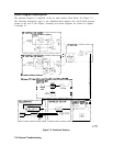
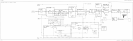
The IF section processes the 10.7 MHz output of the RF section and sends the detected video
to the ADC/interface section. The following major assemblies are included in this section:
A3 interface assembly
A4 log amplifier/calibration oscillator assembly
A5 IF assembly
The spectrum analyzer uses trace-data manipulation to generate the 5
dB/DIV
scale from
the 10
dB/DIV
scale. The A3 interface assembly amplifies and offsets the 10
dB/DIV
video
to generate the 2
dB/DIV
scale. The 1
dB/DIV
scale is generated from the 2
dB/DIV
scale
through trace data manipulation. The first 50 dB of IF gain (log and linear mode) is achieved
using the A5 assembly linear step-gain amplifiers. The A4 assembly video-offset circuit
provides the remaining 60 dB of log mode IF gain. The A4 assembly linear amplifiers provide
40 dB of linear mode gain. IF gain steps of less than 10 dB (regardless of the reference level)
are accomplished on the A5 assembly.
A4 Log Amplifier/Cal Oscillator Assembly
The A4 log amplifier has separate log and linear amplifier paths. After amplification,
the signal path consists of a linear detector, video log amp, buffer amplifier, video offset,
and video buffer amplifier. Other auxiliary functions include the frequency counter
prescaler/conditioner,
the AM/FM demodulator, and down-conversion to 4.8 kHz for digital
resolution bandwidths of
1
Hz through 100 Hz.
The cal oscillator, which is part of A4, supplies the stimulus signal for automatic IF
adjustments. Normally, the oscillator operates only during retrace (for a few milliseconds)
to adjust part of the IF. (All IF parameters will be re-adjusted approximately every five
minutes.) With continuous IF adjust on, a group of IF parameters are adjusted during each
retrace period (non-disruptive). If continuous IF adjust is off, the most recent IF calibration
data will be used.
The IF parameters adjusted include step gains, log amplifier gain and offset, bandwidth
centering, 3 dB bandwidth, bandwidth amplitude, crystal-filter symmetry, and oscillator
frequency used in 1 Hz through 100 Hz resolution bandwidths.
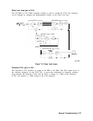
The cal oscillator output has three forms (all -35
dBm):
n 10.7 MHz
m
9.9 to 11.5 MHz in 100 kHz steps
n Frequency sweeps from 20 kHz to 2 kHz centered at 10.7 MHz (lasting 5 to 60 ms
respectively)
The purpose of these signals is to:
n Adjust gains, log amps, and video slopes and offsets.
n Adjust 3 dB bandwidth and center frequencies of LC resolution BW filters (30 kHz through
1 MHz).
n Adjust 3 dB bandwidth, symmetry, and gain of the crystal resolution BW filters (300 HZ
through 10
kHz).
n Adjust gain and gain-vs-frequency for digital resolution bandwidths (1 Hz through 100 HZ).
7-46 General Troubleshooting