


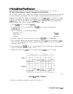
Long
Lines
Dimmer
Than
Short
Lines
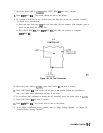
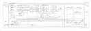
Refer to function block M of A2 controller schematic diagram (sheet 1 of 4) in the
HP 8560 E-Series Spectrum Analyzer Component Level Information.
The Z output function block contains the absolute value circuits which determine the intensity
of vectors drawn on the display. The vector length is approximated by the sum of the X
length and Y length. The voltage corresponding to the X length, AX, is converted to current
by R274. If the voltage is negative, it is amplified by 2 in A2U210C, converted to current by
A2R246, and added to the current from A2R274. This effectively turns both negative and
positive voltages into positive currents, hence absolute value.
1. Short A2J201 pin 13 to ground
(A2TP3).
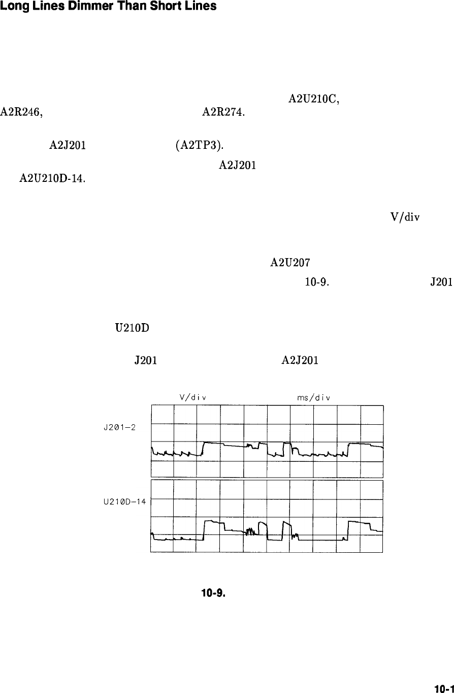
2. Connect channel A of an oscilloscope to A2J201 pin 2. Connect channel B to
A2U210D-14.
3. Set an oscilloscope to the following settings:
Amplitude scale . . . . . . . . . . . . . . . . . . . . . . . . . . . . . . . . . . . . . . . . . . . . . . . 10
V/div
Sweep time . . . . . . . . . . . . . . . . . . . . . . . . . . . . . . . . . . . . . . . . . . . . . . . . . ..lms/div
Triggering . . . . . . . . . . . . . . . . . . . . . . . . . . . . . . . . . . . . . . . . . . . . . . . . . . ..External
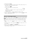
4. Externally trigger the oscilloscope off the signal at A2U207 pin 8 (LBRIGHT).
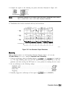
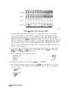
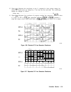
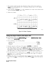
5. The waveforms should look like those illustrated in Figure
10-9.
If the waveform at
J201
pin 2 is bad, troubleshoot the X line generator (function block D of the A2 controller
schematic, sheet 1 of 4).
6. If the waveform at U210D pin 14 is bad, troubleshoot the Z output circuit (function block
M of A2 controller schematic, sheet 1 of 4).
7. Remove the short from J201 pin 13 to ground. Short A2J201 pin 1 to ground.
J’201-2
U210D-
10.0
V/div
0.00 v 1.00
ms/div
0.000 s
SK198
Figure
10-9.
Delta X Waveform
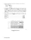
8. Move the oscilloscope channel A probe to 5201 pin 14.
Controller Section
10-l
1