4. IF Amplitude Adjustments
The IF amplitude adjustments consist of the cal oscillator amplitude adjustment and the
reference 15
dB
attenuator adjustment.
Assembly
Adjusted
A4 log
amp/Cal
oscillator
A5 IF assembly
Related
Performance
Tests
IF Gain Uncertainty
Scale Fidelity
Description
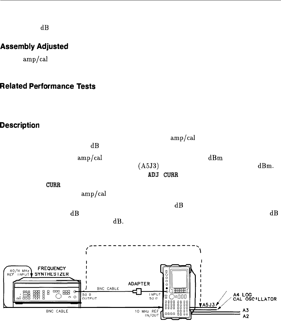
This adjustment sets the output amplitude of the A4 log
amp/Cal
oscillator and the absolute
amplitude of the reference 15 dB attenuator.
The output of the A4 log
amp/Cal
oscillator is adjusted so that a -55
dBm
signal applied to
the 10.7 MHz IF input on the A5 IF assembly
(A5J3)
causes a displayed signal of -60
dBm.
The effect of this adjustment is visible only after the
ADJ
CURR
IF STATE sequence is
complete. ADJ
CURR
IF STATE causes the IF gain adjustment to use the “new” output
amplitude from the A4 log
amp/Cal
oscillator.
This procedure also sets the attenuator of the reference 15 dB attenuator so that a source
amplitude change of 50 dB combined with a spectrum analyzer reference level change of 50 dB
displays an amplitude difference of 50 dB.
TEST CABLE
:
----------------------,
\
I
SPECTRUM I
ANALYZER
’
RTF?
A5 IF BOARD
/
/
El
LoG
n4P
AMP/
’
’
‘LLATOR
SK16
Figure 2-7. IF Amplitude Adjustment Setup
2-26 Adjustment Procedures
