


6
Major Assembly and Cable Locations
Introduction
This chapter identifies the instrument assemblies and cables and contains the following figures:
Figure
6-
1.
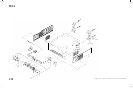
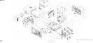
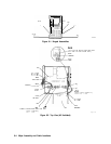
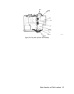
Hinged Assemblies
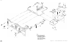
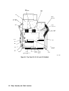
Figure 6-2. Top View (A2 Unfolded)
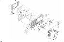
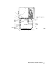
Figure 6-3. Top View (A2 and A3 Unfolded)
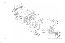
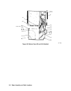
Figure 6-4. Top View (A2, A3, A4, and A5 Unfolded)
Figure 6-5. Bottom View (Al5 Unfolded)
Figure 6-6. Bottom View (Al5 and Al4 Unfolded)
Figure 6-7. Al6 Fast ADC (Option 007)
Figure 6-8. HP 8562E Front End
Figure 6-9. Rear View
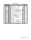
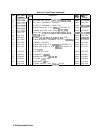
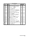
Use the list below to determine the figure(s) illustrating the desired assembly or cable.
Assemblies
.......................................................
..Figur
e
Alfrontframe
.......................................................
..6- 6
AlAlkeyboard
......................................................
..6- 6
A2 controller
......................................................
6-1,6-2
A3 interface
.......................................................
6-1, 6-2
A4 log amplifier/Cal oscillator
........................................ 6-1, 6-3
A5IFfilter
......................................................
..6-1.6- 4
A6 power supply
.......................................................
6-4
A6Al
high voltage module
..............................................
6-4
A7 first LO distribution amplifier (SLODA)
................................
6-8
A8 low band mixer
.....................................................
6-8
A9RF
attenuator
....................................................
..6- 8
A10 Yig-tuned filter/mixer (RYTHM)
....................................
6-8
AllYTO
...........................................................
..6- 8
Al2 (NOT ASSIGNED)
Al3 second converter
...................................................
6-8
Al4 frequency control
............................................... 6-1, 6-6
Al5 RF
.......................................................
6-1,6-5,6-6
Al6 fast ADC (Option 007)
.............................................
6-7
Al7
CRTdriver
......................................................
..6- 4
A18 CRT assembly
....................................................
.6-4
Major Assembly and Cable Locations
6-1