


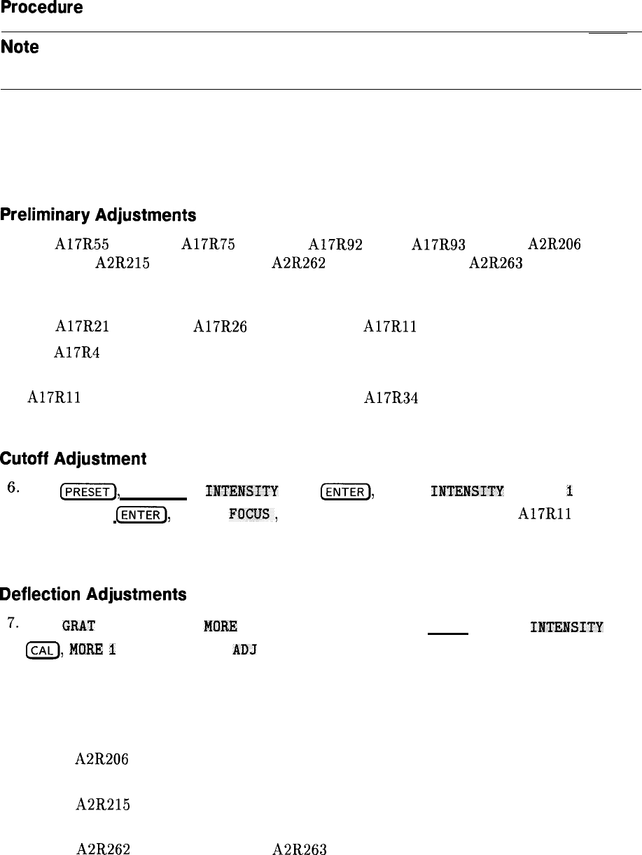
2. Display Adjustment
Procedure
Note
Perform the 16 MHz PLL Adjustment in this chapter before proceeding with
this adjustment.
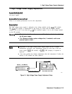
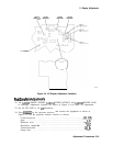
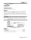
1. Turn the spectrum analyzer off by pressing (LINE). Remove the spectrum analyzer cover
and fold out the A2 controller and A3 interface assemblies as illustrated in Figure 2-2.
Connect the CAL OUTPUT to the INPUT. Adjustment locations are shown on the CRT
neck for Al7 adjustments and in Figure 2-4 for the A2 adjustments.
Preliminary
Adjustments
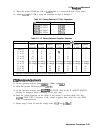
2. Set A17R55 X GAIN, A17R75 Y GAIN, A17R92 DDD, A17R93 ASTIG, A2R206 DGTL
X GAIN, A2R215 DGTL Y GAIN, A2R262 STOP BLANK, and A2R263 START
BLANK to midrange. Also set the rear-panel X POSN, Y POSN, and TRACE ALIGN to
midrange.
3. Set A17R21 Z FOCUS, A17R26 X FOCUS, and
A17Rll
CUTOFF to midrange.
4. Set A17R4 Z GAIN fully clockwise.
5. Turn the spectrum analyzer on and allow it to warm up for at least 3 minutes. Adjust
A17Rll
CUTOFF until the display is visible and A17R34 COARSE FOCUS for best
possible focus.
Cutoff
Adjustment
6.
Press
(PRESET),
(DISPLAY),
IImNSITY
, 255
(ENTER),
STORE
IIfTEMSITY
, MORE
1
of 2,
FOCUS, 127
[ENTER),
STORE
FOCTJS,
then GRAT OM OFF (OFF). Adjust
A17Rll
CUTOFF
until the retrace line between the bottom of trace A and the annunciators at the bottom
of the display just disappears.
Deflection
Adjustments
7.
Press
GRAT
ON OFF (ON),
MORE
2 of 2 , INTENSITY, 80 (ENTER), STORE
INmSITY
,
ICAL),
MO&F,
I
of 2 , and CRT
ADJ
PATTERN . Fold up the A3 interface assembly to access
the adjustments on the A2 controller assembly.
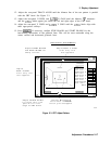
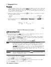
8. Refer to Figure 2-3 for locating the lines used for adjusting DGTL X GAIN and DGTL Y
GAIN. Each of these lines is actually two lines adjusted for coincidence. The two lines will
form an “X” if they are not adjusted properly.
9. Adjust A2R206 DGTL X GAIN until the two vertical lines near the left edge of the
display converge to one single line.
10. Adjust A2R215 DGTL Y GAIN until the two horizontal lines near the top edge of the
display converge to one single line.
11. Adjust A2R262 STOP BLANK and A2R263 START BLANK for the sharpest corners of
the outer box in the test pattern. The intensity of the corners should be the same as the
middle of the lines between the corners.
2-16 Adjustment Procedures