


6. Sampling Oscillator Adjustment
Assembly
Adjusted
Al5 RF assembly
Related
Performance
Test
There is no related performance test for this adjustment procedure.
Description
The sampling oscillator tank circuit is adjusted for a tuning voltage of 5.05 Vdc when the
sampling oscillator is set to 297.222 MHz. The voltage monitored is actually the tuning
voltage divided by 4.05. The setting is then checked at other frequencies for the full tuning
range of the sampling oscillator.
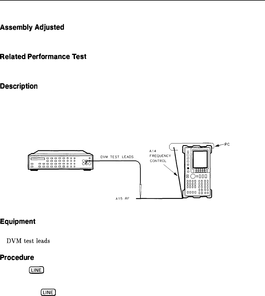
DIGITAL VOLTMETER
SPECTRUM ANALYZER
-
PC
BOARD
PROP
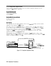
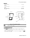
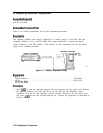
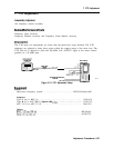
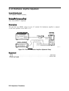
Figure 2-11. Sampler Adjustment Setup
SK17
Equipment
Digital voltmeter . . . . . . . . . . . . . , . . . . . . . . . . . . . . . . . . . . . . . . . . . . . . . . . . HP 3456A
DVMtestleads
. . . . . . . . . . . . . . . . . . . . . . . . . . . . . . . . . . . . . . . . . . . . . . . . HP 34118A
Procedure
1. Press
@
to turn the spectrum analyzer off and disconnect the line power cord. Remove
the spectrum analyzer cover and fold down the Al5 RF and Al4 frequency control
assemblies. Prop up the Al4 frequency control assembly. Reconnect the line power cord
and press
(LINE]
to turn the spectrum analyzer on.
Connect the equipment as illustrated in
Figure 2-11.
2-34 Adjustment Procedures