


Video
Trigger
Comparator
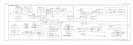
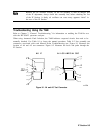
Refer to function block M of the Al6 fast ADC assembly schematic diagram in the
HP 8560 E-Series Spectrum Analyzer Component Level Information.
This 8-bit digital magnitude comparator, U34, compares the digitized samples from the flash
ADC (latch U29 output) to the programmed video trigger level. The video trigger level value
on IOB2 through IOB7 is latched into the P input (top portion of U34) by the firmware on
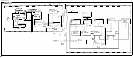
the A2 controller assembly when the fast ADC is in “read” mode. When the sample on the Q
input is higher than the video trigger level on the P input, V-HI output is high, and V-LO
output is low. When the Q input is lower than the P input, V-HI output is low and V-LO
output is high. And when P is equal to Q, both V-HI and V-LO are low. These two signals
(V-HI and V-LO) go to PAL
Ul
(block A) and are used to clock the video trigger generator
(block D).
ADC/lnterface
Section 8-39