


Cal Oscillator (P/O A4 Assembly)
The cal oscillator on the A4 assembly supplies the stimulus signal for automatic IF
adjustments. Normally, the oscillator operates only during retrace (for a few milliseconds) to
adjust part of the IF. (All IF parameters are to be readjusted about every 5 minutes.) With
continuous IF adjust ON, a group of IF parameters are adjusted during each retrace period
(non-disruptive). If continuous IF adjust is OFF, the most recent IF calibration data is used.
The IF parameters adjusted include step gains, log amplifier gain and offset, bandwidth
centering, 3 dB bandwidth, bandwidth amplitude, and crystal-filter symmetry.
The cal oscillator provides three types of output signals (all -35
dBm):
n 10.7 MHz
n 9.9 to 11.5 MHz in 100 kHz steps
n Frequency sweeps from 20 kHz to 2 kHz centered at 10.7 MHz (lasting 5 to 60 ms
respectively)
The signals perform the following functions:
n Adjust gains, log amps, and video slopes and offsets.
n Adjust 3 dB bandwidth and center frequencies of LC resolution bandwidth filters (30 kHz
through 1 MHz).
n Adjust 3 dB bandwidth, symmetry, and gain of the crystal resolution bandwidth filters
(300 Hz through 10
kHz).
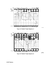
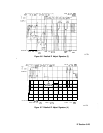
The cal oscillator uses a phase-locked loop (PLL). The oscillator (function block X) is locked
to the instrument 10 MHz reference. The reference divider (function block U) divides the
reference and delivers a 100 kHz TTL signal to the phase detector (function block V). The
divide-by-N circuitry (function block Y) divides the oscillator output of 9.9 MHz to 11.5 MHz
(by 99 to 115)
resulting in a 100 kHz output to the phase detector. When the cal-oscillator
PLL is locked, narrow positive and negative of equal width pulses occur at the phase detector
output. Since the phase detector drives a low-input impedance at the loop integrator, observe
the positive pulses at A4CR808 anode and negative pulses at A4CR809 cathode.
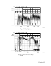
The loop integrator acts as a low-pass filter that filters the pulses and inverts the result. If the
anode of A4CR808 is more positive (with respect to ground) than the cathode of A4CR809 is
negative, the loop integrator output should saturate to approximately -13 V. Conversely, if
the anode of A4CR808 is less positive than the cathode of A4CR809 is negative, the integrator
should saturate to a positive voltage.
Note
If error messages
ERR 581 AMPL
or
ERR 582 AMPL
appears, refer to error
message ERR 582 AMPL in Chapter 7, “General Troubleshooting,” and perform
the procedure provided.
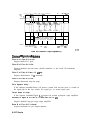
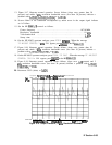
1. The oscillator output frequency should exceed 11.5 MHz if the CAL OSC TUNE line,
A4U804 pin 14, exceeds
+9
V. The oscillator frequency should be less than 9.9 MHz if
CAL OSC TUNE is below -9 V. The oscillator only operates when
CALOSC-OFF
is low
(0
v>*
9-32 IF Section