


22. To remove the divided-down 100 MHz signal from the phase/frequency detector, short
R595. Refer to function block X of Al5 RF schematic.
Check the 100 MHz lock loop integrator (steps 23-27)
23. Remove 10 MHz reference input to the phase/frequency detector by pressing
(ZKYiKCTRL),
EEAE
PAEEL,
and
10
MHZ
EXT. No signal should be connected to the rear-panel 10 MHz
REF IN/OUT connector.
Note
The outputs of phase/frequency detector are low-pass filtered to reduce the
10 MHz component of the signal. The filtered signals are then integrated by
U506
and the result is fed to the tune line of the 100 MHz VCXO.
24. Check that the voltage on A15J502 pin 3 is less than 0 Vdc. Refer to function block P of
Al5 RF schematic.
25. Press
@KYiK],
REAR
PANEL,
and 10
MEz
INT and remove the divided-down 100 MHz
input to the phase/frequency detector by shorting R572.
26. Check that the voltage on A15J502 pin 3 is greater than 13 Vdc.
27. If the loop is locked, the voltage on A15J502 pin 3 should be between 0 and
+6
Vdc.
28. If the front-panel CAL OUTPUT amplitude is out of specification and cannot be brought
within specification by adjusting A15R561, CAL AMPTD, check the calibrator AGC
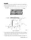
amplifier with the following steps. Refer to function block W of Al5 RF schematic.
Note
The 300 MHz CAL OUTPUT signal comes from the tripled 100 MHz which is
passed through a leveling loop. The 300 MHz signal passes through a low-pass
filter for reducing higher harmonics. These harmonics can fool the detector.
The 300 MHz signal passes through a variable attenuator controlled by PIN
diode CR503 which is controlled by the feedback loop. Diode CR504 is the
detector diode (the same type as CR505). Diode CR504 provides temperature
compensation between the reference voltage and the detected RF voltage.
a. Measure the level of 300 MHz at Al5 TP505 with an active probe/spectrum analyzer
combination. If the signal is less than
+2
dBm,
repeat the first 27 steps of this
procedure.
b. If the signal at this point is correct, place a short across the PIN diode CR503.
c. If the signal level at the CAL OUTPUT is still less than -10
dBm
with CR503 shorted
out, troubleshoot the RF forward path through amplifier
Q505.
(The signal amplitude
decreases.)
d. If the CAL OUTPUT signal level is greater than -10
dBm,
troubleshoot the PIN
diode attenuator, the detector, or the feedback path.
29. Measure the detector voltage at A15J502 pin 14. The voltage should measure
approximately
to.3
Vdc when the CAL OUTPUT signal is at -10
dBm.
This voltage
should change with adjustment of A15R561, CAL AMPTD.
30. Check that the voltage at U507A Pin 3 is
t1.7
Vdc. If this voltage is not correct, there
may be a problem with the
+lO
V reference.
11-18 Synthesizer Section