


Check 10 MHz reference to phase/frequency detector (steps 9-14)
9. On the spectrum analyzer, press
(mCTRL),
REAR
PANEL , and
10
MHz
INT .
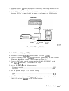
10. Check the 10 MHz reference frequency-accuracy by connecting a frequency counter to
A15J301 and verify that the reference frequency is 10 MHz
f40
Hz after a 5 minute
warmup period.
11. If a 10 MHz signal
>l
V peak-to-peak is not present at A15J301, refer to the “10 MHz
Reference” in Chapter 12, “RF Section.”
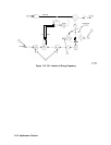
12. Measure the signal at TP301 with an oscilloscope. Refer to function block M of Al5 RF
schematic.
13. Measure the signal at
U502
pin 11 with an oscilloscope. Refer to function block X of Al5
RF schematic. This signal should be TTL levels at 10 MHz with a 60 percent duty cycle.
14. If TTL-level signals (approximately 10 MHz) are not present, check signals backwards
through the loop to find a fault in the signal path.
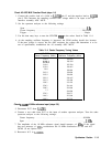
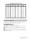
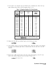
15. Measure the signals at the following test points with an active probe/spectrum analyzer
combination:
Junction of
C570
and C571
100 MHz, +2.5 dBm
f2
dB
Junction of R715,
R716, R567, and R568
100 MHz, -3
dBm
f2
dB
U700
pin 3 100 MHz, +16.5 dBm
f2
dB
U700
pin 1
100 MHz, +8.5 dBm
f2
dB
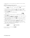
16. If an approximately 10 MHz TTL signal is present at
U502
pin 11 with 60 percent duty
cycle, and the RF portion of the phase-lock loop is functioning, the fault probably lies in
the phase/frequency detector or the 100 MHz lock loop integrator.
Check phase/frequency detector (steps 17-22)
17.
18.
19.
20.
21.
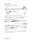
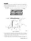
Monitor
U504
pin 5 and
U503
pin 9 with an oscilloscope. These are the two outputs of
the phase/frequency detector. Refer to function block 0 of Al5 RF schematic.
A locked loop will exhibit stable, narrow (approximately 20 ns wide), and positive-going
TTL pulses occurring at a 10 MHz rate at U504 pin 5 and
U503
pin 9.
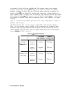
If the loop is unlocked, but signals are present on both inputs of the phase/frequency
detector, the output pulses will be superimposed on each other.
If the loop is unlocked, and there is no signal at one of the phase/frequency detector
inputs, one phase detector output will be at TTL low and the other will be at TTL high.
For example, if there is no input signal at U504 pin 3,
U504
pin 5 will be TTL low and
U503
pin 9 will be TTL high. If there is no input signal at
U503
pin 11,
U503
pin 9 will
be TTL low and U504 pin 5 will be TTL high.
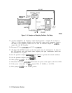
To remove the 10 MHz reference input to the phase/frequency detector, press
(AUXCTRL),
EEAE
PANEL, and
10
M&
EXT
with no signal applied to the rear-panel 10 MHz REF
IN/OUT connector.
Synthesizer Section
11-17