


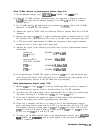
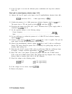
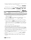
13. If the IF signal is not near the indicated power, troubleshoot the loop mixer (function
block AI).
Check path to phase/frequency detector (steps 14-19)
14. Measure the loop IF signal at the input to the IF amplifier/limiter (function block AK):
A15L428
(end nearest U411)
4 MHz (approximately -6
dBm)
15. Confirm the presence of a 4 MHz square-wave reference frequency signal at
U406
pin 3.
The square wave is TTL and should go below
to.6
V and above
t2.2
V.
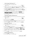
16. Disconnect the jumper from X201 pins 1 and 5. Disconnect the dc power supply which is
connected to A15J200 pin 16.
17. Set the spectrum analyzer to the following settings:
Center frequency
. . . . . . . . . . . . . . . . . . . . . . . . . . . . . . . . . . . . . . . . . . . .
..300MHz
Span
. . . . . . . . . . . . . . . . . . . . . . . . . . . . . . . . . . . . . . . . . . . . . . . . . . . . . . . . . . . . 0 Hz
18. Use an oscilloscope to confirm the presence of a 4 MHz TTL-level reference frequency
signal at
U406
pin 11.
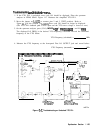
19. Connect a short across A15R425. Connect A15U406 pins 3 and 11 together. This puts the
same signal on both the phase/frequency detector inputs.
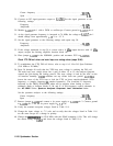
20. Observe the phase/frequency detector outputs,
U406
pins 6 and 9, with an oscilloscope.
Narrow TTL pulses should be present. Pin 9 is normally low, pulsing high, and pin 6 is
normally high, pulsing low.
21. Check the end of L417 (
nearest
C445) with an oscilloscope. With the oscilloscope input
ac-coupled, a triangle waveform approximately 20
mVp-p
should be present.
22. Short C441 with a wire jumper. (Connect the jumper from the end of R462 nearest
C441 to the end of R460 nearest C443.) This changes the loop integrator into a voltage
follower. Refer to function block AB of Al5 RF schematic.
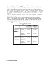
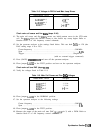
23. Check the voltages at the following points:
A15U408
pin 6
+2.5
Vdc (approximately)
A15X201
pin 1
+2.5
Vdc (approximately)
24. If the voltages are not correct, suspect A15U408.
25. Remove the jumpers.
11-22 Synthesizer Section