


Procedure 13. Rear Frame/Rear Dress Panel
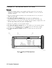
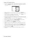
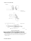
4. Place the coax cable BNC connectors into the appropriate rear frame holes as described
below. Use a
9/16-inch
nut driver to attach the dress nuts holding the BNC connectors to
the rear frame.
Rear Panel Jack RF Cable
W24, coax 5
W23, coax 93
1
W25, coax 4
W18,
coax 97
W31, coax 8
W58, coax
0
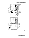
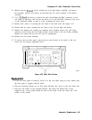
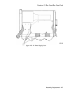
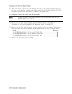
5. Secure the rear frame to the spectrum analyzer main deck, using four
panhead
screws (1).
See Figure 4-22.
6. Secure the rear frame to the spectrum analyzer side frames using three
flathead
screws per
side. Use caution to avoid damaging any coaxial cables.
7. Place the spectrum analyzer top-side-up on the work bench.
8. Pull the red and black battery wires through the rear frame battery-assembly hole. Solder
the red wire to the positive lug of the battery-assembly, and the black wire to the negative
lug. Replace the battery.
9. Secure the battery assembly to the rear frame, using two
flathead
screws.
10. Connect the fan and line-power cables to A6J3 and
A6JlOl
on the A6 power supply.
11. Snap the
A6AlW3
post-accelerator cable to the CRT assembly.
12. Snap the black grommet protecting
A6AlW3
into the CRT shield.
13. Ensure that all cables are safely routed and will not be damaged when securing the A6
cover.
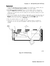
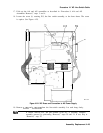
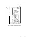
14. Secure the power-supply cover shield to the power supply, using three
flathead
screws (1).
One end of the cover fits into a slot provided in the rear frame assembly. Ensure that the
extended portion of the cover shield is seated in the shield wall groove. See Figure 4-23.
15. Connect the HP-IB cable to A2J5.
16. Fold the A2, A3, A4, and A5 assemblies into the spectrum analyzer as described in
procedure 5.
4-46 Assembly Replacement