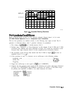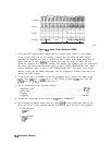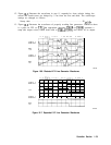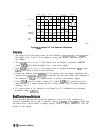
1. Disconnect W22 from A2J8.
2. If a 10 MHz, TTL-level signal is not present at the end of W22, continue with step 3. If a
10 MHz signal is present at W22, proceed as follows:
a. Reconnect W22 to A2J8.
b. Set the spectrum analyzer to the following settings:
Span . . . . . . . . . . . . . . . . . . . . . . . . . . . . . . . . . . . . . . . . . . . . . . . . . . . . ..ZeroSpan
Sweep time . . . . . . . . . . . . . . . . . . . . . . . . . . . . . . . . . . . . . . . . . . . . . . . . . . . . 20ms
c. Monitor the signal at A2J2 pin 21. This is an output of the frequency counter,
HBUCKET PULSE.
d. If HBUCKET PULSE is stuck high, troubleshoot the frequency counter.
3. Check for a 10 MHz signal at A15J302. If the signal is not present at A15J302, the Al5 RF
assembly is probably defective.
State- and Trace-Storage Problems
State storage is in the two of the four Program
RAMS
and trace storage is in the two display
RAMS.
With low battery voltage, it is normal for states and traces to be retained if the power
is off for less than 1 minute. If the power is left off for more than thirty minutes with low
battery voltage, the stored states and traces will be lost. The following steps test battery
backup:
1. Measure the voltage on W6 at
A2JlO.
If the voltage is less than 2.6 V, check the
BTl
battery.
2. If the battery voltage is correct, reconnect W6 to
A2J10,
turn the analyzer power off and
wait 5 minutes.
3. Measure the voltage at
A2UlOl
pin 28 and A2U102 pin 28.
4. If the voltage is less than 2.0 Vdc, the RAM power battery-backup circuitry on the A2
controller assembly is probably at fault.
Controller Section lo-15


