


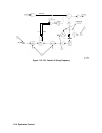
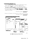
9. If the signal is not measured near the indicated power, troubleshoot the offset lock loop
buffer (function block AM of Al5 RF schematic sheet 3 of 4).
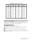
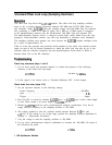
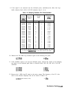
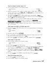
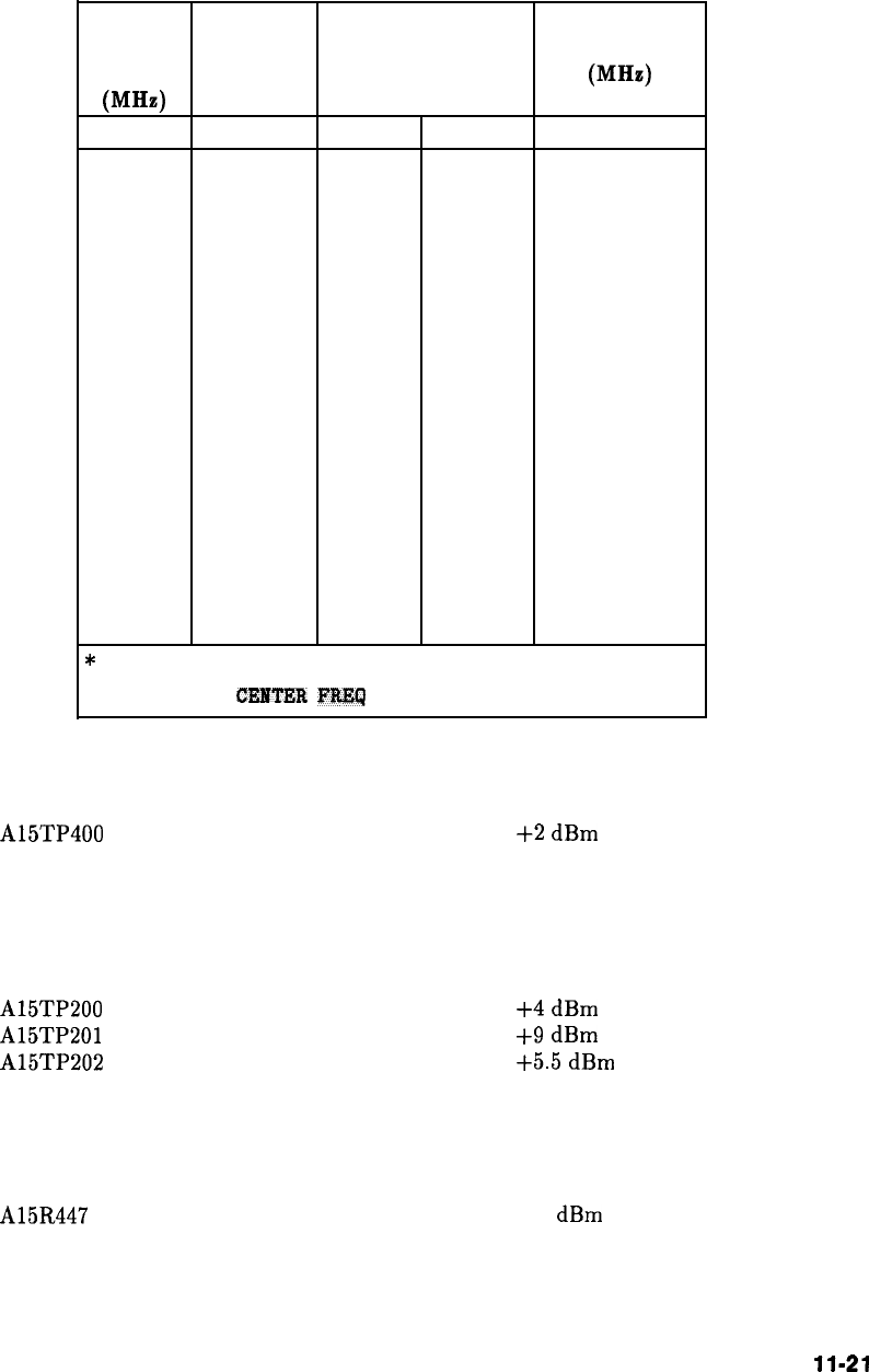
Table 11-6. Sampling Oscillator PLL Divide Numbers
sampling
Center
Reference
Reference
Oscillator Frequency*
Divide
Frequency
Frequency (MHz)
Chain
(MHz)
(MHz)
Prescaler Postscaler
285.000
2156.3
10
2
15.000
286.364
2176.3
11
2
13.636
287.500
2199.5
8
3
12.500
288.462
2230.3
13
2
11.538
288.888
799.3
9
3
11.111
290.000
2263.3
10
3
10.000
290.909
2282.3
11
3
9.091
291.666
2302.3
9
4
8.333
292.500
2155.3
8
5
7.500
293.478
2158.3
23
2
6.522
294.444
2336.3
9
6
5.556
295.000
2196.3
10
6
5.000
296.000
1.3 15
5
4.000
296.471
2378.3
17
5
3.529
297.000
2410.3
20
5
3.000
297.222
2422.3
18
6
2.778
’
To set the sampling oscillator to a desired frequency, set span
to 0 Hz and
CENTER
FREQ
to the value listed in the table.
1
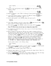
10. Measure the 296 MHz loop feedback signal at the following test point:
A15TP400
+2
dBm
11. If the feedback signal is not near the indicated power, measure the signals at the following
test points on the feedback path. Refer to function blocks AD, AG, and AH of Al5 RF
schematic.
A15TP200
A15TP201
A15TP202
+4
dBm
+9
dBm
+5.5
dBm
12. Measure the 4 MHz loop-IF signal at the mixer output. The frequency of the IF is the
same as the reference frequency and can be found in Table 11-6.
A15R447 (end nearest L414)
-6
dBm
Synthesizer Section
11-21