


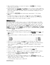
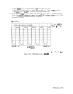

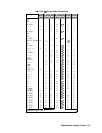
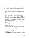
Table 13-1.
Wl
Power-Cable Connections (continued)
Signal
A2Jl A3Jl A4Jl A5Jl A6Jl A14Jl A15Jl
(Pin.9
(pins)
(PW
(Pms) (Pins) (Pins) (Pms)
+5
v
12 39
-
-
39*
-
-
+5
v
11 40
-
-
40*
-
-
+5
v
10 41
-
-
41’
-
-
+5
v
9
42
-
-
42*
-
-
+5
v
8
43
-
-
43*
-
-
+5
v
7
44
-
-
44*
-
-
+28
V
6
45
-
-
45*
-
-
LINE TRIGGER
-
46
-
-
46*
-
-
+15
v
4
47
-
-
47*
-
-
+15
v
3
48
-
-
48*
-
-
-15 v
2
49 49
-
49*
-
-
-15 v
1
50 50
-
50*
-
-
*
Indicates signal source.
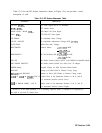
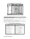
Table 13-2. Automatic Fault Isolation References
Suspected Circuit Indicated
Manual Procedure to Perform
by Automatic Fault Isolation
Check A2 controller
Blanking signal
Check all power supply outputs
Dead power supply (steps 1-5)
Check buck regulator
Dead power supply (steps 22-23)
Check buck regulator control circuitry
Dead power supply (steps 11-21)
Check high voltage supplies
High voltage supplies
Check input rectifier
Dead power supply (steps 6-7)
Check intensity adjustments
Intensity problems (steps l-4)
Check kick start/bias circuitry
Dead power supply (steps 8-10)
Check low voltage supplies
Low voltage supplies
Troubleshooting Using the TAM
Refer to Chapter 7,
“General Troubleshooting,” for information on enabling the TAM for use
with the HP 85623 Spectrum Analyzer.
When using automatic fault isolation, the TAM indicates suspected circuits that need to be
manually checked. Use Table 13-2 to locate the manual procedure.
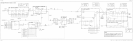
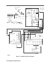
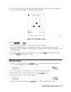
Table 13-3 lists assembly test connectors associated with each manual probe troubleshooting
test. Figure 13-2 illustrates the location of Al7 test connectors.
13-4 Display/Power Supply Section