


Procedure 9. Al4 and Al5 Assemblies
Caution
DO NOT fold the board assemblies out of the spectrum analyzer one at a
time. Always fold the Al4 and Al5 assemblies as a unit. Folding out one
assembly at a time binds the hinges attaching the assemblies and may damage
an assembly and hinge.
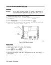
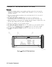
4. The board assemblies are attached to the right side frame of the spectrum analyzer with
two hinges. Fold both the Al4 and Al5 assemblies out of the spectrum analyzer as a unit.
5. Remove all cables from the assembly being removed.
6. Remove the two screws that attach the assembly being removed to its two mounting hinges.
Caution
DO NOT torque shield screws to more than 5 inch-pounds. Applying
excessive torque will cause the screws to stretch.
Replacement
1. Attach the removed assembly to the two chassis hinges with two
panhead
screws.
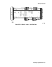
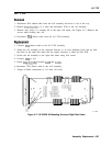
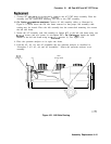
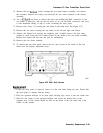
2. Attach all cables to the assembly as illustrated in Figure 4-19. Torque the
W34/A15
SMA
connection to 113 Ncm (10 in-lb).
3. Lay the Al4 and Al5 assemblies flat against each other in the folded out position. Make
sure that no cables become pinched between the two assemblies. Ensure that all coaxial
cables are clear of hinges and standoffs before continuing onto the next step.
4. Fold both board assemblies into the spectrum analyzer as a unit. Use caution to avoid
damaging any cable assemblies.
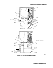
5. Secure the assemblies using the eight screws removed in
“Removal” step 3. See Figure 4-18.
6. Secure the spectrum analyzer cover assembly as described in “Procedure 1. Spectrum
Analyzer Cover.”
4-38 Assembly Replacement