


Digital Signature Analysis (DSA)
Digital signature analysis (DSA) places microprocessor, A2U1, in a simplified known state.
This simplified state consists of placing a one-word instruction, MOVE QUICK, (0111
xx10 xxxx
XXXO)
on the data bus. The microprocessor cycles through its address
range continually reading the instruction. Perform the following DSA procedure to test the
operation of microprocessor, A2U 1:
1. Press (LINE) to turn the spectrum analyzer off.
2. Move the DSA jumper on J3
(1
ocated
in the middle of the A2 assembly) from the
DISable
position to the
ENAble
position.
3. Remove jumper
A2El.
A2El
is a 16 pin dual-in-line package located in the middle of the
A2 Assembly. Press (LINE) to turn the spectrum analyzer on.
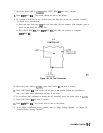
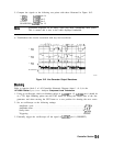
4. Use an oscilloscope to confirm that address lines, address strobe, and chip selects are
toggling at proper levels.
5. Use an oscilloscope to check the address line sequencing. The signal on each line (starting
with Al and ending with A23) should be one-half the frequency of the previous line.
6. If step 4 reveals problems, microprocessor
A2Ul
is probably faulty.
7. Press (LINE) to turn the spectrum analyzer off. Replace jumper
A2El.
Move the DSA
jumper from connecting E5 and E6 back to connecting E6 and E7.
Display Problems
Line
Generators
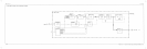
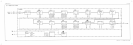
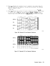
Refer to function blocks D and I of A2 controller schematic diagram (sheet 1 of 4) in the
HP 8560 E-Series Spectrum Analyzer Component Level Information.
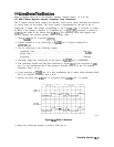
The line generators convert the digital display information to an analog output suitable to
drive the Al7 CRT driver assembly. These circuits change the digital words into vectors,
or lines, which move the beam of the CRT. The vectors are each 6 ps long (width of the
INTEGRATE pulse) followed by a 1
~LS
SAMPLE pulse. When characters of text are being
drawn, the vectors are 3 ps long.
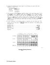
1. On the spectrum analyzer, press
(PRESET).
2.
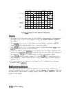
On the spectrum analyzer, press
ICAL)
MORE CRT ADJ
PATTIE@.
If the display is blank,
press the bottom
softkey
and then the top softkey.
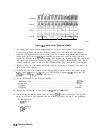
3. Set an oscilloscope to the following settings:
Amplitude scale
. . . . . . . . . . . . . . . . . . . . . . . . . . . . . . . . . . . . . . . . . . . . . . . .
.3
V/div
Sweep time
. . . . . . . . . . . . . . . . . . . . . . . . . . . . . . . . . . . . . . . . . . . . . . . . . . . . 1
ms/div
Triggering
. . . . . . . . . . . . . . . . . . . . . . . . . . . . . . . . . . . . . . . . . . . . . . . . . . . . . External
4. Externally trigger the oscilloscope off the signal at A2U207 pin 8 (LBRIGHT).
10-4
Controller Section