


4
Assembly Replacement
This chapter describes the removal and replacement of all major assemblies. The following
replacement procedures are provided:
Access to Internal Assemblies
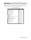
Cable Color Code
Procedure 1. Spectrum Analyzer Cover
Procedure 2. Al Front Frame/Al8 CRT
Procedure 3.
AlAl
Keyboard/Front Panel Keys
Procedure 4.
AlA
RPG
Procedure 5. A2, A3, A4, and A5 Assemblies
Procedure 6. A6 Power Supply Assembly
Procedure 7.
A6Al
High Voltage Assembly
Procedure 8. A7 through Al3 Assemblies
A7 First LO Distribution Amplifier
A8 Low Band Mixer
A9 Input Attenuator
A10 YIG-Tuned Filter/Mixer (RYTHM)
All YTO
Al3 Second Converter
Procedure 9. Al4 and Al5 Assemblies
Procedure 10. Al6 Fast ADC and Al7 CRT Driver
Procedure 11.
Bl
Fan
Procedure 12.
BTl
Battery
Procedure 13. Rear Frame/Rear Dress Panel
Procedure 14. W3 Line Switch Cable
Procedure 15. EEROM (A2U501)
Procedure 16. A21 OCXO (Non-Option 103)
Tools required to perform the procedures are listed in Table 4-l.
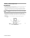
The words right and left are used throughout the replacement procedures to indicate the side
of the spectrum analyzer as viewed from the front panel.
Numbers in parentheses are used throughout the replacement procedures to indicate numerical
callouts
on the figures.
Caution
The spectrum analyzer contains static-sensitive components. Read the section
entitled, “Electrostatic Discharge” in Chapter 1, “General Information.”
Assembly Replacement 4-1