


3. IF
Bandpass
Adjustment
Note
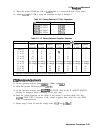
If the range for the XTAL CTR adjustment is insufficient, replace the
appropriate factory-selected capacitor as listed in Table 2-8. To determine
the correct replacement value, center the XTAL CTR adjustment, and press
AD.?
GUM IF STATE. After the IF ADJUST STATUS message disappears, read
the DVM display. Choose a capacitor value from Table 2-9, based on the
DVM reading and the presently loaded capacitor value. Table 2-10 lists a few
capacitor part numbers.
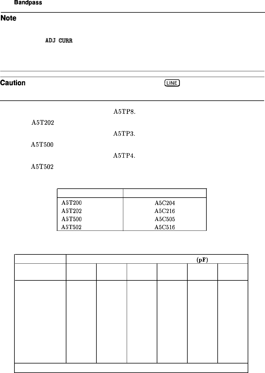
Caution
Turn the spectrum analyzer off by pressing
LLINE)
to the off position before
removing or replacing any shield.
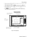
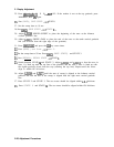
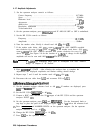
18. Move the positive DVM test lead to
A5TP8.
19. Adjust A5T202 XTAL CTR 2 using the procedure in steps 15 through 17.
20. Move the positive DVM test lead to
A5TP3.
21. Adjust A5T500 XTAL CTR 3 using the procedure in steps 15 through 17.
22. Move the positive DVM test lead to
A5TP4.
23. Adjust A5T502 XTAL CTR 4 using the procedure in steps 15 through 17.
Table 2-8. Factory-Selected XTAL Filter Capacitors
XTAL CTR Adjustment Fixed Factory Select Capacitor
A5T200 XTAL CTR 1
A5C204
A5T202 XTAL CTR 2
A5C216
A5T500 XTAL CTR 3
A5C505
A5T502 XTAL CTR 4
A5C516
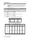
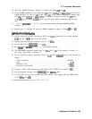
Table 2-9. XTAL Factory-Selected Capacitor Selection
DVM Reading (V)
Currently Loaded Capacitor Value (pF)
Replace Replace
Replace
Replace Replace Replace
15
with:
18
with:
20
with:
22
with:
24
with:
27
with:
0 to 1.5
*
*
*
*
*
*
1.5
to
2.5
27
*
*
* *
*
2.5
to
3.5
22
27
27
* *
*
3.5
to
4.5
18
22
24
27 27
*
4.5
to
5.5
18
20
22
24 27
*
5.5 to 6.5
No change No change No change No change No change No change
6.5 to 7.5
No change No change No change No change No change No change
7.5
to
8.5
*
15
18
18
22
24
8.5
to
9.5
*
15
15
18
20
24
9.5
to
10
*
*
15
18
20
24
* Indicates a condition that should not exist; suspect broken hardware.
2-24 Adjustment Procedures