


31. Measure voltage at U507B pin 5 while adjusting R561. This is the
temperature-
compensated adjustable voltage reference to which the detected voltage is compared. It
should vary between
+0.15
V and i-O.6 V.
32. Adjust R561 to its limits and verify that the output U507B pin 7 measures approximately
+1
Vdc at one limit and -12 Vdc at the other limit.
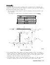
Third LO Driver Amplifier
The third LO driver amplifier (Q503)
amplifies the 300 MHz from the 300 MHz distribution
amplifier to a sufficient level to drive the LO port of the double balanced mixer. During the
SIG ID operation, diodes CR501 and CR502 turn off the 3rd LO driver amplifier in order to
minimize the amount of 300 MHz going to the double-balanced mixer.
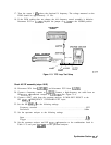
Check level at amplifier input (steps 1-6)
1. Press (mCTRL_), INTERNAL MIXER. Press
SIG
ID OFF, if Option 008 is installed.
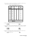
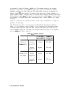
2. Use an active-probe/spectrum-analyzer combination to confirm the power level of the
300 MHz signal at the following test points:
A15X602
pin 5
>+7
dBm
A15TP504
>+15
dBm
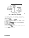
3. If the signal at A15X602 pin 5 is low, but the signal at
A15TP504
is correct, press
(mCTRL),
INTEENAL
MIXER . Press SIG ID OFF , if present.
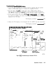
4. Check that PIN diode switches CR603 and CR605 are reverse biased by approximately
+lO
Vdc. Refer to function block F of Al5 RF schematic.
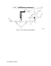
5. Measure 300 MHz signal at
A15TP503
using an active probe/spectrum analyzer
combination. If the signal is not approximately i-10
dBm,
refer to “Unlocked Reference
PLL” in this chapter.
6. If the level at the TP503 is correct, but signal at TP504 is too low, the fault is probably in
the amplifier.
Synthesizer Section 11-19